Although ultrasonic measurements have been in use for borehole imaging, in openhole and cased-hole wireline for more than three decades, they could not be used in highly deviated wells and hostile environments.
Thus, efforts have been made to develop ultrasonic LWD imaging devices that are no longer dependent on the type of drilling mud or standoff such as LWD resistive imaging tools. It was also important to obtain a resolution of the image that would allow accurate identification of stratigraphic, structural and tectonic stress direction indicators.
The ultrasonic amplitude image has helped in identification of the most stratigraphic, structural and tectonic stress orientation features. Travel time measurements were oriented to create a truth borehole shape. Breakout direction was determined with the help of the potato plot and confirmed the direction of those determined on the amplitude image. In-situ tectonic stress direction elements, drillinginduced fractures and tensile zones have been identified alongside breakouts, the first two indicating maximum tectonic stress direction.
Method and theory
A high-frequency ultrasonic transducer acts as a transmitter and receiver to provide measurements of travel time and amplitude. In this way, the ultrasonic transducer provides borehole images across 128 sectors using travel time measurements and 128 sectors’ formation images using amplitude measurements, with a 360-degree borehole coverage.
The sound pulse generated by the transducer travels through the mud to the borehole wall where it is reflected and travels back to the transducer. The travel time is the time it takes to make this journey and is used to provide the caliper measurement. The standoff between the tool and borehole wall is calculated as mud velocity multiplied by arrival time of the first reflection from the borehole wall divided by two.
The second measurement is the detection of formation features (beddings and fractures) and borehole breakouts from the change in signal amplitude. The amplitude of the reflected wave is a function of the acoustic impedance of the medium, which is defined as the velocity times the density of the medium. The higher the impedance of the medium, the higher the amplitude and vice versa. The presence of a fluid gap (vugs or fracture) causes the amplitude to decrease due to the lower acoustic impedance of the fluid compared to the rock. The relative change in amplitude is proportional to the width of the fluid gap.
The travel time and amplitude measurements of the ultrasonic waves are a function of several factors such as mud slowness, standoff and acoustic impedance variations.
Case study
The analyzed well is situated in the northern Weald Basin in Surey, southern England. The 57⁄8-in. sidetrack well started from a maximum inclination of 69 degrees and dropped to 2 degrees, drilled with oil-based mud. The 4¾ in. LWD high-resolution ultrasonic imaging tool recorded the data in a stored memory while reaming the well without affecting the rig activity as powered by batteries thus independent from mud flow.
The interpretation of ultrasonic amplitude and travel time images from memory has led to the accurate identification of stratigraphic, structural and in-situ tectonic stress indicator features. Bedding, crossbedding disconformities, natural fractures, vugs, breakouts, induced fractures and tensile zones have been identified and classified. Most of the picked features have been identified on the amplitude image, and some of them were confirmed by travel time measurements. Borehole breakouts, drilling-induced fractures and tensile zones were identified as in-situ tectonic stress indicators. Borehole breakouts (Figure 1) could be distinguished on the amplitude image as low acousticamplitude zones developed 180 degrees apart around the borehole wall. Also, the oriented potato plot derived from travel time measurements may offer indications related to borehole ovalization. In this way, breakouts are determined from two different methods that confirm each other.
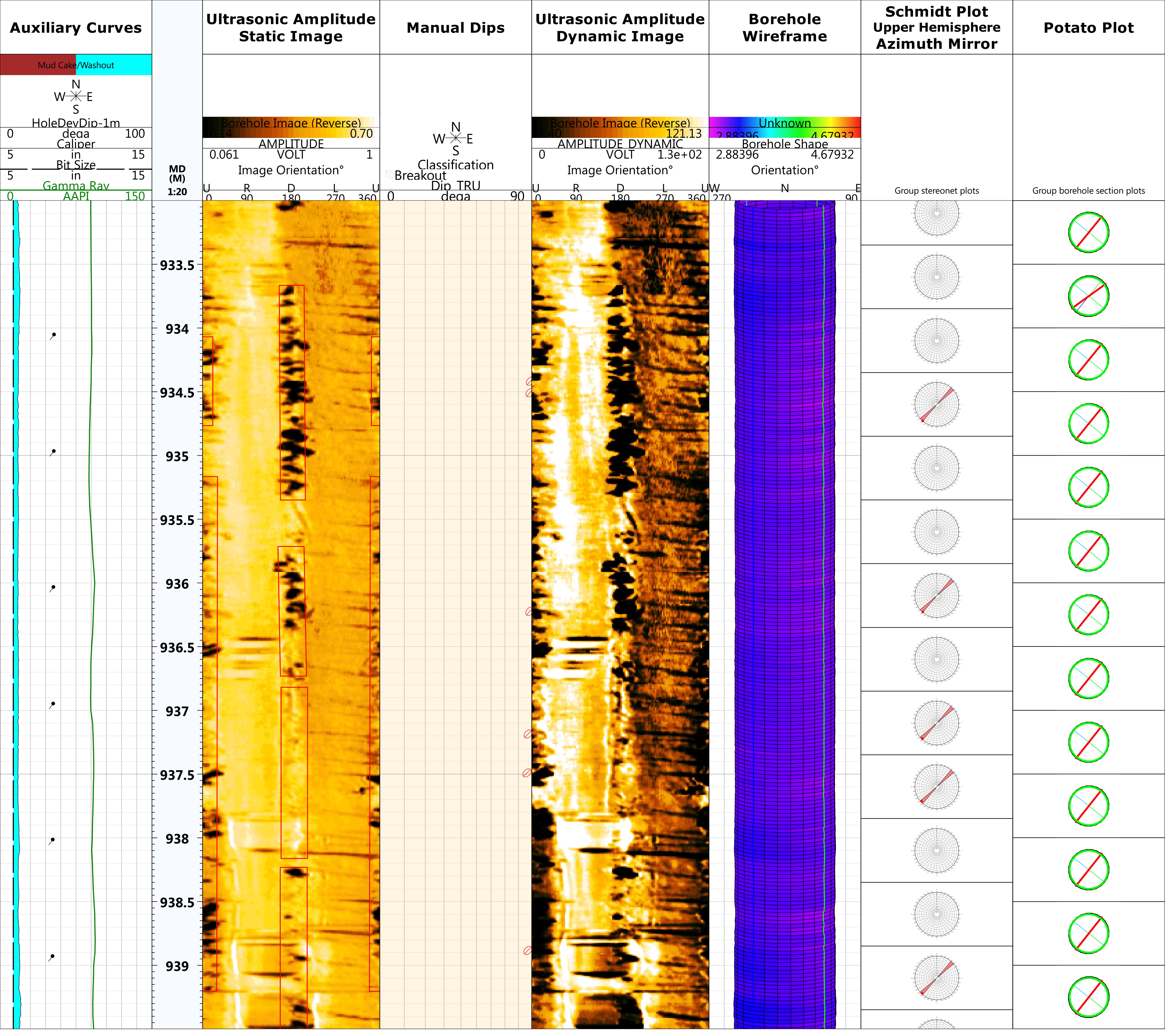
Drilling-induced fractures (Figure 2), developed 180 degrees apart around the borehole and 90 degrees from breakouts, are created when the stress concentrated around the borehole exceeded that required to cause tensile failure of the wellbore wall. They represent a typical maximum stress direction indicator. Drilling-enhanced fractures, which are pre-existing natural fractures that reopen or its apertures are enhanced because of drilling, in-situ imbalance or thermal contraction, have the same orientation as drilling-induced fractures and confirm the maximum stress direction.

Conclusion
Borehole instability phenomena become even more critical in the current economic environment because of the need to mitigate all nonproductive time factors to deliver optimized wells with respect to costs.
The new LWD ultrasonic imaging represents a powerful instrument for detection of wellbore stability parameters both in water- and oil-based mud in hole sizes ranging from 57⁄8-in to 8¾-in. In-situ tectonic stress elements were both detected on amplitude image and deduced from borehole ovality analysis. The determination of borehole breakouts as magnitude and orientation contributes to the validation or adjustment of the geomechanical predrill model and the selection of the optimal parameters for the drilling mud. As a result of the borehole shape analysis, two key seat zones were identified generated by large dogleg values. These observations helped drillers to understand the borehole conditions to avoid issues during the casing job.
Recommended Reading
Green Light: NatGas Industry Just Fine, TG Natural Resources CEO Says
2024-03-27 - Craig Jarchow, president and CEO of TG Natural Resources, updated the integration status of its $2.7 billion acquisition of Rockcliff Energy and addressed macro concerns about the natural gas business at Hart Energy’s DUG GAS+ Conference and Expo in Louisiana.
Venture Global, Grain LNG Ink Deal to Provide LNG to UK
2024-02-05 - Under the agreement, Venture Global will have the ability to access 3 million tonnes per annum of LNG storage and regasification capacity at the Isle of Grain LNG terminal.

DUG GAS+: Chesapeake in Drill-but-don’t-turn-on Mode
2024-03-28 - COO Josh Viets said Chesapeake is cutting costs and ready to take advantage once gas prices rebound.

Total CEO: US LNG Shaky, Global Projects Brought into Spotlight
2024-02-21 - U.S. President Joe Biden’s decision to pause approvals for new U.S. LNG projects benefits similar projects around the world and casts doubt around U.S. supply, TotalEnergies’ Pouyanné told analysts during the company’s quarterly webcast.
ARC Resources Adds Ex-Chevron Gas Chief to Board, Tallies Divestments
2024-02-11 - Montney Shale producer ARC Resources aims to sign up to 25% of its 1.38 Bcf/d of gas output to long-term LNG contracts for higher-priced sales overseas.