
Figure 1. A 3x48megawatt VSDS systems, supplied by ABB for gas-export compressors, is back-to-back tested for the Ormen Lange project.
Those in the natural gas business know that gas is becoming a truly global commodity as volumes are increasingly transported around the world in the form of liquefied natural gas (LNG). As a result, top-level reliability at the source location becomes ever more critical.
Gas turbines have traditionally been the preferred drivers for large refrigerator compressors used for liquefaction, but that is changing. Recently, the classic system of directly coupled compressors and gas turbines on a single shaft has begun to be less attractive because of limitation in availability and flexibility due to high maintenance restrictions and missing spinning redundancy.
Meanwhile, variable speed drives and electrical motors, used mainly as turbine starters and helpers, were considered to be potential solutions for the LNG-production applications sector.
As environmental constraints, such as those for carbon emissions and energy efficiency, are becoming more restrictive, the classic solution is getting even less convenient. Yet, even with these considerations, obstacles existed for source companies that wished to migrate to LNG liquefaction plants with full electrical-driven compressors (E-LNG).
The largest obstacle is that such plants will require a constant availability of adequate electrical performance and capacity. Such availability was only recently made possible by advances in technology. Today, this has drastically changed the mode of thinking about and approaching the LNG process.
The continuous improvements in power electronics and the availability on the market of large frequency converters (up to 100 megawatt), paved the way for large variable speed drive systems (VSDS), an ensemble of transformer, variable frequency drive and motor) which are now most often considered for new designs as main compressors driver solution. These provide flexibility by allowing variable speed operations, strong reliability and lower maintenance costs.
An E-LNG solution requires the presence of a reliable source of power. Since plants are often built in remote areas where no interconnection to a public power network is available, in many instances dedicated combined-cycle power plants and electrical systems have to be built locally to generate, transmit and distribute the power to utilities in this “island” configuration.
Control systems also play an important role in this solution. Not only VSDS but all high-, medium- and low-voltage equipment like switchgears, transformers and power-factor compensation banks benefit from fast and reliable power management systems. Also, integration of the VSDS controller and its diagnostics with the plant-control system need to be adequately implemented for improved control and performance. Pre-study is essential to confirm parameters and to select main power-system components. Once pre-study is accomplished, the rest of life cycle, starting from project execution, requires constant monitoring with rigorous quality standards for system integration, test and site operations. This article mainly addresses high power application for large refrigerant compressors in LNG plants, where compressor shaft power is above 30MW and can even reach 65MW and higher (Figure 1).
Advantages of a full-electrical solution
For LNG plants, except in rare cases, electric energy is not available from a nearby power station or reliable public grid. However, it can be produced in the plant itself by using large commercial power-generation gas turbines in the 100 megawatt (MW) range. In a combined-cycle power plant, electric energy efficiency is much higher than that obtained when operating in single-cycle with modified aircraft turbines in the 25 MW range —the typical configuration when a gas turbine is used to directly drive a compressor. Local power generation is sufficient to cover the needs of a full-electrical solution.
The same is true when the plant can be interconnected to the national transmission system, where the interconnection can be backed up by in-plant generation.
VSDS are more efficient than gas turbines and require less maintenance. This results in higher uptime and maintenance-cost reduction. Other factors that influence the decision to use VSDS are the benefits derived from their high reliability and excellent control properties. VSDS can easily drive compressors over the typical operating speed range of 70% to 105%, allowing for high flexibility and operability.
Also, turbines cannot start by themselves and 20 MW or higher electrical drivers are needed to start the turbine, as well as help it handle reduced output during high ambient temperatures. Finally, the high efficiency of the VSDS allows for a remarkable reduction of CO2 and NOx emissions, thus helping plants to comply with environmental rules.
Typical configuration
In the power range above 30 MW, the typical VSDS configuration consists of using the load machine-commutated inverter (LCI) frequency converter. In 1997, ABB delivered a 101 MW LCI, the largest in operation at the time, for the wind tunnel at NASA.
The LCI system, based on synchronous machines and converters with naturally commutated thyristors, is one of the most efficient drive systems that exist. The LCI converter is generally chosen with a 12-pulse configuration motor side, while the line-side 12-pulse or high-pulse configuration can be adopted (Figure 2).

Figure 2. The LCI 12-pulse configuration is used for large power applications.
Transformer
Transformer technology, the most reliable and efficient electrical machines, has been continuously improved and their design has been validated and proven by thousand of references in several industry fields as well as the energy sector. For VSDS applications, the transformer is of primary importance because it steps down the input-supply voltage to the converter medium-voltage level. At the same time, converter transformers are generally used in multi-winding configurations to allow harmonic cancellation.
For large power applications, transformers are typically oil filled. Different cooling systems can be used dependent on plant location. A typical example is one with a four-windings transformer with one primary and three secondary windings (Figure 2). Two secondary windings feed the converter while the third one feeds the power-factor compensation and harmonic filter. The windings dedicated to the converter are 30-degree phase shifted, thus creating the 12-pulse reaction-line side. The transformer is designed with low impedance between the drive and the filter winding and higher impedance between the primary and secondary windings to minimize harmonic currents transferred from the drive to the supply network. This solution is generally preferable for a large-power VSDS.
Converter
The LCI converter is one of the most reliable drives available. Its proven technology and its large installed base make it perfect for high-power applications. The LCI is based on thyristor technology and has two or more 6-pulse input thyristor rectifiers, depending on chosen line side pulse configuration. Also, it has a DC-Link reactor, two 6-pulse thyristor inverters, a control system, a synchronous motor excitation unit and a cooling unit. The LCI acts as a current source for the motor. The controlled rectifiers are line commutated and the inverters are load-commutated.
The thyristors can be selected in N+1 configuration so that, in the event of a failure, the converter is still capable of providing full power, thus increasing the availability of the system. The DC-reactor serves to smooth the DC current as well as to reduce fault currents in the DC-link. It is typically an iron-core type and is integrated in the LCI cubicle. The motor-excitation unit feeds the motor’s brushless exciter and is directly controlled by the converter-control system.
For these high power applications, the LCI is water cooled. The internal-cooling system has the following objectives:
• Purify the water from the internal water circuit to a low-conductivity level as required by the electrical components.
• Pump the de-ionized water to the electrical components of the converter (e.g. heat sinks of thyristors, snubber resistors and reactors in rectifier, dc-link and inverter) where it takes up heat losses.
• Transfer the heat losses, via a deionized water/raw water heat exchanger, to the external raw water circuit.
Brushless motors
Brushless two-pole synchronous motors with solid rotors are the preferred choice for very large compressor applications. Their construction derives from the proven and well- established large-turbo generator design and technology. Typically, the synchronous motor has two electrical 30-degree phase-shifted windings that are suitable for 12-pulse inverter connections. This configuration allows for the reduction of the shaft-torque ripple produced by the non-linear frequency converter.
The excitation is fed via the excitation unit in the LCI. Typically, brushless excitation is chosen. The excitation is made of a tri-phase stator winding (the exciter machine), fed by the LCI excitation unit. The exciter winding itself, which is generating the rotating field, is fed via the exciter machine and the rotating diode bridge.
A totally enclosed machine is the preferred choice, given the harsh and aggressive environment present in most LNG plants. Depending on the plant location and on the environmental conditions such as ambient temperature, water availability and type of installation, either a totally enclosed air-to-water cooled CACW motor or a totally enclosed air-to-air CACA motor can be selected

Figure 3. Back-to-back test configuration can vary for suitability.
Power factor compensation and harmonic filter
The LCI converter always absorbs reactive power because of thyristor commutation. The power-factor line side of the LCI is typically between 0.8 and 0.9, depending on the VSDS load conditions. Also, the LCI injects harmonic currents into the supply network, which depends on the pulse configuration. In order to cope with these two factors, a twelve-pulse converter configuration is typically chosen for large power application. This way, the transformer can be designed with an additional secondary winding connected to a power-factor compensation and harmonic filter. The power factor compensation and harmonic filter has the primary function to compensate for the LCI reactive-power consumption. The rating in kVAr of the filter is chosen in order to guarantee specified performance in terms of power-factor line side of the VSDS.
The choice of the filter composition, including the number of branches and tuning, depends on harmonic analysis to reduce to the injection of current harmonics by VSDS into the grid as much as possible. The filter is usually made of different branches properly tuned over chosen resonance frequencies.
Pre-commissioning test
VSDS should be extensively factory tested to uncover any possible hidden weakness of components and system design before delivery. All the VSDS components should be subject to routine tests during the factory acceptance test. Type tests for the motor and transformer are usually also performed.
The complete VSDS line-up should be full-load tested before string test with the compressor to prove system electrical performances and control functionalities. The LCI converter is an inherent 4-quadrant converter, meaning it can be operated in motor and braking mode, which suits the back-to-back test configuration. The VSDS is run in a back-to-back configuration with a second, similar VSDS, which recycles the power used by the first VSDS to drive the load required. As a consequence, most of the power remains in the process, and only the losses of the two VSDS in operation and the excess reactive power, which is not compensated by the two filter systems, need to be fed from the test-bay supply network.
During the back-to-back test, the VSDS can be tested at full power, which cannot be done during string test since compressor rating is lower that VSDS one. Also, it can be tested at different operating conditions to calculate efficiency and to measure currents and voltages. LCI controller functional tests, as well as simulation of alarm/trip signals to the LCI controller, can be simulated.
Only after having satisfactorily passed these extensive tests can the VSDS can be sent to a compressor manufacturer for a string test where the compressor performances are tested.
Consideration of electrical network
With the introduction of large-frequency converters, power-supply quality has become more of a concern. The presence of harmonics may result in unacceptable supply-voltage distortion responsible for overheating components, insulation stresses and EMC issues. Harmonic studies should be performed to define possible actions needed to keep the harmonic distortion within the limits set by international standards. Depending on the design of the electrical system, a number of harmonic mitigation options can be considered:
Harmonic filters can be designed to provide a low impedance path to the current injections, thus limiting the harmonic currents flowing in the network, and ultimately the total harmonic distortion. Harmonic filters can be directly connected to a switchboard or to a tertiary winding on each converter transformer. For large-power VSDS that are generally connected to high voltage bus, typically greater than 33 kilovolt (kV), this solution is preferable.
Otherwise, when several identical VSDS are present, pulse systems can be achieved by the judicious choice of transformer primary-windings phase shifts. This solution limits the number of harmonic injections. But, to achieve full harmonic cancellation, all drives should be in operation and equally loaded.
Another solution can be a common switchboard, known as a “dirty board.” It can be dedicated to feed large variable speed drives and other significant harmonic sources. The objective is to contain the harmonic distortion to this switchboard by supplying it via a high-impedance transformer.
When performing harmonic analysis, special care should be given to the presence of cables. In full-electrical-solution LNG plants, where power is generated within the plant, the voltage is stepped up to high voltage to allow transmission to nearby facilities. Often this is done with high-voltage cables whose intrinsic stray capacitance may be responsible for parallel resonances that, when hit by the injected harmonic currents, are responsible for unacceptable voltage distortion, which affects power transmission quality. The same may be done if the LNG plant is interconnected to the national grid, where power is already received at high voltage.

Figure 4. Old control-system architecture was applied to full-electric compression.
Network studies
Most of the time, E-LNG plants have no grid connection and must be supplied under island conditions. The in-plant generation should be chosen in an (N+1) generation configuration so that, in the case of loss of a generator, the system will ride through the transient and reach a new steady-state operating condition without requiring load shedding.
Network studies, such as load flow, transient studies, harmonic analysis and short circuit calculations, should be performed to define the sizing of system components during normal and peak loadings, both for normal and contingency network configurations. These studies benefit from simulations that perform an accurate analysis and modeling of the power plant and take into account both power-control and automatic- voltage regulation. This is important when large VSDS are used. Studies should include those involving the loss of generation, loss of load (in particular the loss of one large VSDS) and fault recovery. Such events could cause a large mismatch in the available power generation and the system load, thus producing severe system frequency and voltage swings.
Automation and control
The adoption of a VSDS-driven compressor will also introduce a very important modification in the process-control architecture of a compressor train. The most common control architecture is still based on an old concept, where DCS is considered to be a slow-cycle-time machine and is in charge only of slow-control feedback loops such as fuel valves for turbines to set rotational speed.
On the other side of the classical-control concept, the fast-control feedback loops are assigned to special external dedicated hardware such as those only in charge of control of the anti-surge valve. The old control architecture approach is often still applied to VSDS driven compressor. The classical fast-control design includes:
• A DCS in charge to control the LNG process and, in particular, to define the working point.
• A unit control panel, which is the PLC in charge to define rotational speed of the motor and to check the relevant interlocks.
• An anti-surge control that is locally controlling the surge valve in order to avoid surging.
Modern HW/SW architecture-control systems are mature enough to overcome those limitations given by the usage of different HW platforms for different control functionalities. Actually, a modern DCS (for example ABB’s System 800xA), where control cycle time can be also of 1 ms, can cover within the same platform all the functionalities required to control the entire LNG process as well as the fast loop of surge valve. Note that in the case of an existing plant, where slow DCS (cycle time higher than 200ms) is used, it is still useful to have a unique control system for VSDS and surge valve.
The modern approach with unique control system introduces several important advantages:
• Simplification of the maintenance of the automation system by adopting one unique HW/SW platform.
• Simplification of operation by using one unique human-machine interface instead of two or three.
• Increased safety by removing communication links between different HWs.
• The possibility to simplify the system and guarantee a truely redundant operation.
• Improved performance by using all the benefits provided by an integrated control system.
Integrated control system and process optimization
An integrated control system can improve process performance by taking advantage of consolidating all available information and managing all control loops in a coordinated way. This is very important due to two process modifications that result from the adoption of VSDS as compressor driver:
• A VSDS system for compressor trains significantly improves the response time when compared to gas turbine driven alternatives (electric motor has typical speed step response time of less than 200 ms).
• A VSDS allows for operation in a much wider operating speed range where the electrical drive and motor efficiency stay relatively constant.
In this way, motor-speed and surge-valve controls can be operated as interacting control loops, both in steady-state and during dynamic transitions. Consequently, a VSDS solution balances power requirements faster and better among the different sections of the LNG process. Better control results in both increased process safety and process efficiency. Furthermore, for load sharing optimization, when multiple compressors are employed in parallel, the possibility to operate on a wider speed range allows for the load sharing control solutions to have access to those operating points, which will minimize the total power consumed by the compressors.
Advanced surge control
The typical surge-avoidance and control methods result in recirculation valves being used extensively and being opened widely well before the compressor is actually in danger of reaching surge. A VSDS allows for a new strategy based on an active surge control scheme by using the motor torque as a manipulated variable. By using the fast response time of the motor as much as possible, and the surge valve in a coordinated way, it is possible to improve anti-surge performance and allow the compression systems to operate with lower recirculation flows with an increase in energy efficiency.
This is not only a possibility, but it is probably an obligation, because the improved VSDS response time is a benefit from one side, but it may result in dynamic interaction between VSDS and surge-valve control loops, and could turn in mutual disturbance. This interaction was not present in turbine-driven compressors, since turbines have slower response times compared with surge valves so the two control loops are decoupled from the operative control-frequency point of view.
Asset monitoring
The compressor and the VSDS are critical equipments in an LNG plant and must be continuously monitored in real time. The monitoring systems consist of hardware and software layers. The hardware layer is an industrial computer properly interfaced with the DCS, pressure and flow rates and the VSDS. The software layer automatically collects and analyzes selected signals and parameters for abnormalities such as changes in drive status, faults and unexpected stoppages, signals crossing threshold values and user-defined parameter changes. It triggers alarms for the operators.
The signals available at high frequencies can also help trace back disturbances such as flow-induced vibrations, which can then enable preemptive measures to be taken before the disturbance can damage the equipment. In addition to continuous monitoring and analysis of the compressor’s and VSDS’s state and operation, asset monitoring systems can also provide advanced functionalities such as root-cause analysis of past alarms or automatic planning of maintenance schedules. Combination of all these asset-monitoring options increases the reliability of the combined VSDS and compressor system.
Torsional vibration damping
High dynamic performance of full-electric driven compressor also brings new challenges. Some plants have experienced a torsional vibration in mechanical chain compressors. This is a typical situation that occurs when high-performance drives are introduced. In these cases, a good control system becomes the best weapon to monitor and solve vibration problem. This is done with a mix of offline tools to analyze the overall processes, such as fluid-dynamic, mechanical, electrical, and control systems, and online-control functions to measure and solve the problem.
Anti-vibration control systems are a mix of function to avoid exciting resonance frequencies and to modify the physical characteristics of the process. ABB is in the process of patenting one of these systems.
Authors
Paolo Belli and Daniele Buzzini, Oil, Gas and Petrochemical Business Unit, ABB SpA (Italy); and Mehmet Mercangoez, Corporate Research, ABB Switzerland
Recommended Reading
TotalEnergies Starts Production at Akpo West Offshore Nigeria
2024-02-07 - Subsea tieback expected to add 14,000 bbl/d of condensate by mid-year, and up to 4 MMcm/d of gas by 2028.
US Drillers Add Oil, Gas Rigs for Third Time in Four Weeks
2024-02-09 - Despite this week's rig increase, Baker Hughes said the total count was still down 138 rigs, or 18%, below this time last year.

NAPE: Turning Orphan Wells From a Hot Mess Into a Hot Opportunity
2024-02-09 - Certain orphaned wells across the U.S. could be plugged to earn carbon credits.
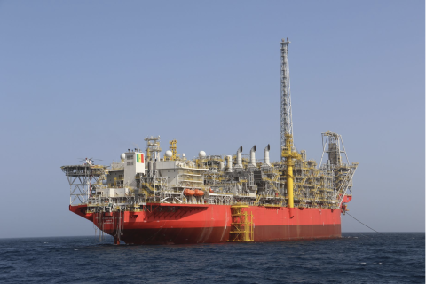
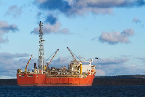
Sangomar FPSO Arrives Offshore Senegal
2024-02-13 - Woodside’s Sangomar Field on track to start production in mid-2024.
NAPE: Chevron’s Chris Powers Talks Traditional Oil, Gas Role in CCUS
2024-02-12 - Policy, innovation and partnership are among the areas needed to help grow the emerging CCUS sector, a Chevron executive said.