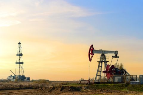
Mature doesn’t have to mean boring. Take the Ekofisk field, for instance. It has had an interesting history since its discovery in 1969, putting Norway on the map as an oil producing giant (Figure 1). The field is an enormous chalk field containing an estimated 6.7 Bbbl of oil. Over time water injection has caused pressure depletion and water weakening, leading to serious compaction. The producing platforms had to be jacked up in 1987 to overcome this subsidence.
The field’s latest claim to fame centers on the use of permanent reservoir monitoring (PRM) to understand compaction in the field. Time-lapse seismic studies in the past have helped analyze the production mechanisms and identify unswept zones for well planning. During a presentation at the 2013 European Association of Geoscientists and Engineers Conference and Exhibition, several authors from ConocoPhillips Norge and Total E&P Norge presented their findings relating to the success of the Ekofisk PRM system.

FIGURE 1. Located in the southern Norwegian North Sea, the Ekofisk field contained an estimated 6.7 Bbbl of oil. (Images courtesy of ConocoPhillips)
Streamer surveys not enough
Ekofisk has been subjected to several 4-D streamer surveys over the years, starting in 1999 when a monitor survey was acquired over the first 3-D survey acquired a decade earlier. The monitor survey indicated significant time shifts in the upper reservoir that were related to reservoir compaction. Three additional streamer surveys were acquired in 2003, 2006, and 2008.
Despite the success of these surveys in showing reservoir compaction, the team determined that the challenging field required more frequent surveys with higher repeatability. After examining several options, it was determined that PRM was the preferred solution despite the high upfront cost. Unlike Valhall and other permanently monitored fields, ConocoPhillips chose fiber-optic instrumentation provided by Optoplan to monitor the field.
Between August and October 2010, the new PRM system was installed. The system has 24 cable lines with a 200-km (124-mile) array and almost 4,000 multicomponent sensors. The cables are trenched 1.5 m (5 ft) into the seabed. The system also includes a containerized recording system.
The authors noted that 94% of the shots are within 5 m (16 ft) of their preplot position.
The topside system houses the optical instrumentation that is used to send light signals to the sensors. A recording system demodulates the signals and creates seismic files. The full array is typically used during active seismic campaigns as well as some passive surveys for monitoring. A smaller array is used for continuous monitoring.
So far six active surveys have been conducted. They use a source mounted on a supply vessel and last 40 to 50 days. Quality control is performed both onsite and onshore. The system can be turned on and operated remotely from shore.

FIGURE 2. A series of consecutive 2-D receiver gathers are shown before (left) and after (right) mitigation processing for the reduced hydrophone pressure response. Weak gathers highlight sensors with a reduced response (red rectangles). After mitigation, no sign of the problem is visible.
Sensors
Several issues cropped up in early surveys. These included reduced hydrophone sensitivity and pressure leakage in some of the accelerometers. The team noted that the pressure response for some of the sensor stations varied between the prime and reshoot lines. Tests indicated that there was an impaired transfer mechanism in the hydrophone chamber. Through collaboration with the vendor, a processing mitigation solution was developed (Figure 2), resulting in data that are comparable to unaffected data.
Once the mitigation solution was put in place, normal root mean square (NRMS, a calculation of repeatability) dropped to 4%, better than anticipated. The lowest NRMS achieved with streamer data was 12%. This has allowed much smaller 4-D effects to be detected.
A repeat processing sequence is used that is the same sequence as the baseline and first monitor surveys. Final stacks are available to the interpreters one month after the final shot is fired.
The team also determined that its interpretation systems needed to be upgraded. It has developed a nonlinear inversion to estimate time strain and intra-reservoir time shifts. Time strain volumes between all pairs of vintage datasets can be calculated quickly once the processed cubes have been received.
The team also developed a Web-based interpretation database that allows quick access to 4-D attributes at any scale. This is enabling greater communication among the various stakeholders.

FIGURE 3. The cumulated time shift on the left is the 4-D signal observed between the first and second PRM surveys after two months of injection. The middle image shows the signal between the second and third surveys, four months apart, and the right image shows the signal between the third and fourth surveys, 10 months apart.
Value of information
What is sometimes lacking from these types of studies is a sense that the information is actually making a difference in the way a field is developed. At Ekofisk, these time-lapse results are routinely used to optimize well locations and trajectories, suggest and prioritize well intervention, diagnose mechanical issues, and update the reservoir model. The data also are used to monitor and survey the impact of injection, production, compaction, and subsidence on the overburden section.
Figure 3 shows the intra-reservoir time shifts in injector well I1. Between the two surveys, a slow-down corresponding to repressurization can be seen in the yellow-red signal. The water front displacement also is visible.
The figure to the right shows no significant signal close to the injector well, indicating that the pressure had stabilized.
Deemed a success
The use of fiber-optic technology in PRM is still a relatively new phenomenon, and this study is likely to clear the path for its increasing use. Authors of the Ekofisk study noted that it was a very positive experience that produced high-quality data and enabled them to tackle the challenges posed by the field. After three years of operation, nearly all of the sensors are still live and providing useful information. The data are being used in field management, well planning, and seismic history-matching, and the success has further improved the company’s attitude toward 4-D surveys.
Acknowledgment
This information was originally presented as paper Tu-08-01 at the 2013 European Association of Geoscientists and Engineers Conference and Exhibition.
Recommended Reading
Tinker Associates CEO on Why US Won’t Lead on Oil, Gas
2024-02-13 - The U.S. will not lead crude oil and natural gas production as the shale curve flattens, Tinker Energy Associates CEO Scott Tinker told Hart Energy on the sidelines of NAPE in Houston.
Chesapeake Enters into Long-term LNG Offtake Agreement
2024-02-13 - Chesapeake Energy entered into a long-term liquefaction offtake sale and purchase agreement with Delfin LNG and Gunvor Group for a 20-year period.
The Secret to Record US Oil Output? Drilling Efficiencies—EIA
2024-03-06 - Advances in horizontal drilling and fracking technologies are yielding more efficient oil wells in the U.S. even as the rig count plummets, the Energy Information Administration reported.
CERAWeek: Gunvor Sees Balanced Oil Market, No Tightness in LNG Supplies
2024-03-18 - The global LNG market is not currently tight, Gunvor Chairman Torbjörn Törnqvist said at CERAWeek, contradicting the view shared earlier in the day by TotalEnergies.
What's Affecting Oil Prices This Week? (March 18, 2024)
2024-03-18 - On average, Stratas Advisors predicts that supply will be at a deficit of 840,000 bbl/d during 2024.


