During a typical well test, flow rates are varied to assess reservoir size and performance. Many fixed and portable test separators utilize a dual chamber orifice fitting for performing the gas flow measurement, but these can be
subjected to less than ideal use practices.
Experienced operators must perform the 30-minute plate changing process every time the flow rate changes significantly. This can result in five to eight gas release events during the testing of a typical exploration well. Some users have expressed safety concerns regarding exposure to flammable and possibly poisonous H2S gas.
To maintain as small a footprint as possible, the space in which the orifice plate meters are installed is also generally very restricted. This can lead to the equipment incorporating several out-of-plane, 90-degree elbows at a distance of eight to 10 times of the pipe diameter (D), upstream of the meter. Essentially, going beyond the requirements set out in the ISO-5167-2 standard.
Most installations try to overcome this issue with a 19-tube bundle flow straightener, generally located five to six pipe diameters, upstream of the orifice plate. However, as ISO-5167-2 recommends these to be placed 13.5 D to 14.5 D upstream, it is highly likely that increased uncertainty is being introduced, especially at low beta (β) ratios. Alternatively, some users have deployed two parallel flowlines, containing meters, valves and instruments, adding to the capital cost, road (or crane) weight and maintenance costs.
Smarter flow measurement
Field operational constraints and functional concerns prompted the development of Adjusta-Cone, a modifiable cone flowmeter by GM Flow Measurement Services Ltd. Applying conventional differential pressure (DP) cone meters as the base technology, a moveable cylindrical sliding sleeve is located within the bore of the meter housing and moves about a fixed position cone.
The sliding sleeve produces two separate but overlapping flow ranges, contained within a single meter body, giving an enhanced turndown ratio. It also boasts reduced installation space—up to 60% less footprint than that of a dual chamber orifice fitting—as well as weight benefits, compared to other meters.
The cone meter automatically self-adjusts to allow fluctuations of flow. In the low range, the sleeve partially covers the cone, and the β ratio is calculated between the cone outside diameter (OD) and sleeve inside diameter (ID). In the high range, the cone is uncovered, and the β ratio is calculated between the meter ID and the cone OD. The large and small β ratios produce one larger operating envelope, from the partial merging of the two individual envelopes.
However, the intelligent measuring tool has two different β ratios and corresponding coefficients of discharge, which are analyzed by the close-coupled flow computer. Aligned with the customer’s choice of applicable standards, the technology computes every second the gas density, compressibility, expansibility, mass and volume flow rate.
Robust technology
Two flowmeters, a 6 in. (0.75 and 0.5β) and 4 in. (0.7 and 0.45β), were built and calibrated at the National Engineering Flow Laboratory (NEL) with dry nitrogen gas, flowing at 10 and 62 Bar (g) (Figure 1). A series of coefficients of discharge and corresponding Reynolds numbers were obtained.
At NEL, calibration was undertaken with the sliding sleeve in both the low and high ranges, and typical mass flow rates used for the 4-in. meter are shown in the table below.
|
β Ratio |
Pressure Bar (g) |
Min Δp (mBar) |
Max Δp (mBar) |
Min qm Kg/sec |
Max qm Kg/Sec |
|
0.45 |
10 |
24 |
500 |
0.222 |
1.01 |
|
0.7 |
10 |
24 |
8501 |
0.86 |
4.96 |
|
0.7 |
61 |
24 |
8501 |
2.04 |
12.002 |
|
0.45 |
61 |
24 |
500 |
0.52 |
2.41 |
1 Field use would limit the differential pressure limit to 500 mBar
2 Limits of the test facility
Data from the dry nitrogen calibration of the meter are shown. (Source: GM Flow Measurement Services Ltd.)
Upon completion of the dry gas calibration, the meter was wet gas tested using N2 and a kerosene substitute to provide an over-reading datum for wet gas operation. Those data were compiled for a Lockhart-Martinelli parameter ranging from 0 to 0.25 and a gas Froude number ranging from 0.4 to 5.2. Selected dry gas results are shown in Figure 1.
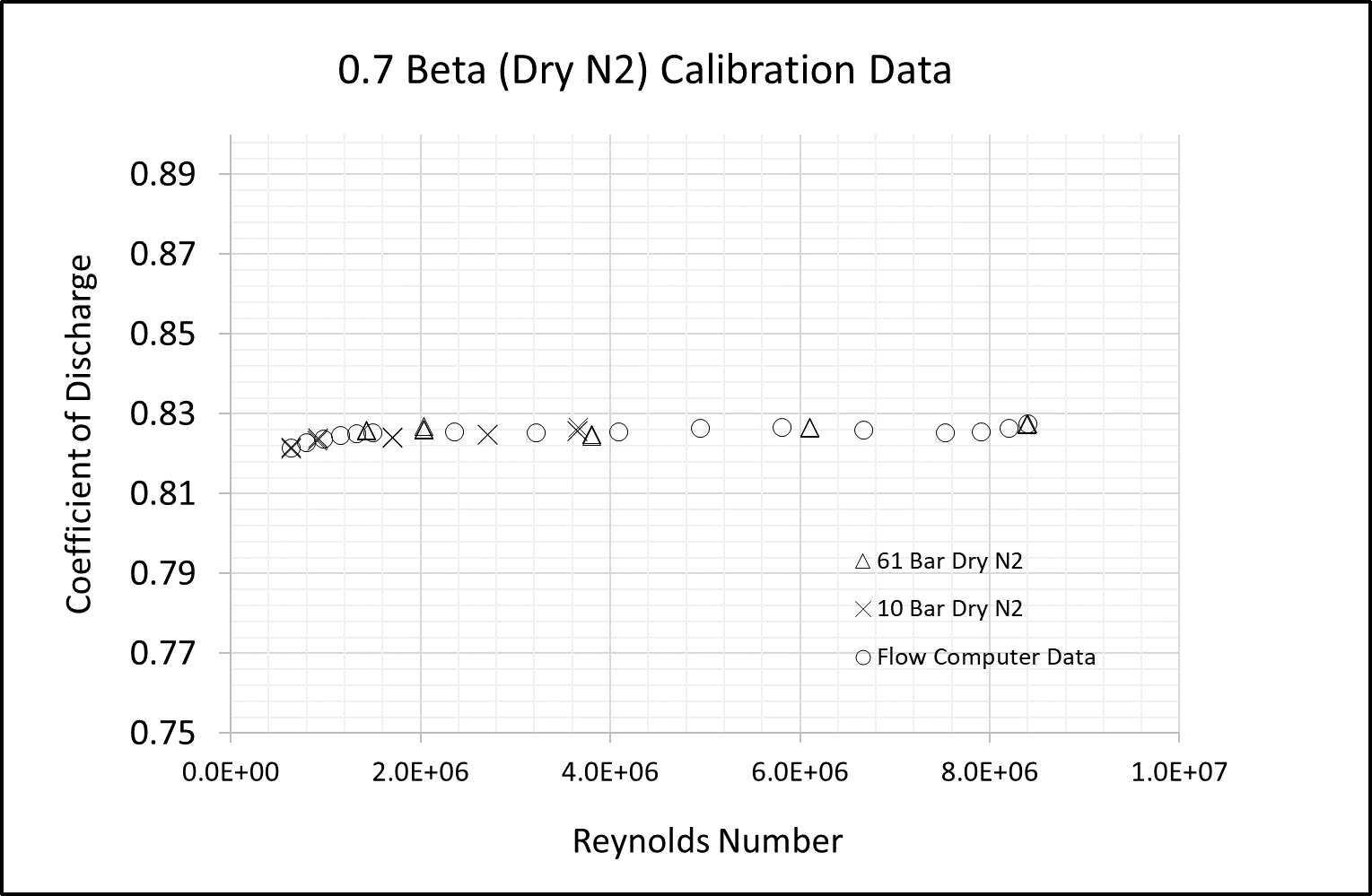
The turndown ratio of the adjustable cone meter was demonstrated as 54.5:1 by mass flow rate (limited by the test facility). The example shows that an average uncertainty 0.49% applies over the calibrated operating range and the average repeatability of points is +/- 0.02%.
Field testing
In 2016 the 6-in. prototype meter was field trialed in the U.K. North Sea. It was installed in two offshore wells downstream of the separator pressure control valve during well testing operations.
The customer’s orifice meter reading, running at 300 psi, was compared to that of the adjustable cone installed downstream of the pressure control valve and running at only 3 psi to 5 psi, which proved to be somewhat inconclusive.
Flow rates from the well tests were significantly lower than expected, so the adjustable cone was also found to be oversized. Readings from the adjustable cone were consistently higher than the orifice readings, largely due to oversizing, low pressure and the presence of moisture in the gas. The results proved that the meter was durable under oilfield conditions and that the sleeve would operate as desired.
Trials are ongoing on the 4-in. production model in the Middle East. Unlike the North Sea trial, in 2018 the meter was installed upstream of the pressure control valve so a direct comparison could be made with the customer’s orifice plate readings.
The adjustable cone meter did not require a shift from the high range for all tests, while upward of 15 hazardous and time-consuming orifice plate changes were required as the flow rates were adjusted, exposing the operators to hazardous gas releases each time.
The adjustable cone meter provided a greater than 55:1 turndown ratio (in one range), which is comparable to expectations for the device. It also showed excellent agreement with the customer’s flow data at consistently better than 0.5% of the orifice plate reading.
Gas metering of the future
Further analysis is underway by GM Flow to fully understand the wet gas effect on different sizes of adjustable cone meters. The company is undertaking additional flow laboratory validation and characterization tests using finite element analysis and computational fluid dynamics to gain deeper insight into the mechanical, hydraulic and physical aspects of the device.
Various adjustable meter designs also are being investigated. This includes the application of advanced materials and manufacturing techniques and the use of artificial intelligence and machine learning software. Real-time remote access and control and wet gas applications also are being explored.
References available.
Contact E&P's Executive Editor Jennifer Presley at jpresley@hartenergy.com for comments or questions about this story.
_____________________________________________________________________________________________
This story first appeared in E&P magazine's "2019 Offshore Technology Yearbook" issue, which published in May. Read the other "2019 Offshore Technology Yearbook" articles:
OVERVIEWS:
Back to Deep Water
Mexico Finding Its Place in Offshore Landscape
Middle East Offshore Market Treads Recovery Path
KEY PLAYERS:
Operators Foresee Vast Potential
TECHNOLOGY:
New Generation of Offshore Drilling Tools Targets Safety, Wellbore Conditions
Platforms Enter a New Cycle
Subsea Sector Recovery Underway
Evolving ROVs
CASE STUDIES:
Advanced Flowmetering (story above)
Composites Gain Ground
PRODUCTION FORECAST:
Americas and Middle East Put Offshore Back on the Map
Recommended Reading

Analyst: Is Jerry Jones Making a Run to Take Comstock Private?
2024-09-20 - After buying more than 13.4 million Comstock shares in August, analysts wonder if Dallas Cowboys owner Jerry Jones might split the tackles and run downhill toward a go-private buyout of the Haynesville Shale gas producer.

BKV Prices IPO at $270MM Nearly Two Years After First Filing
2024-09-25 - BKV Corp. priced its common shares at $18 each after and will begin trading on Sept. 26, about two years after the Denver company first filed for an IPO.

Sheffield: E&Ps’ Capital Starvation Not All Bad, But M&A Needs Work
2024-10-04 - Bryan Sheffield, managing partner of Formentera Partners and founder of Parsley Energy, discussed E&P capital, M&A barriers and how longer laterals could spur a “growth mode” at Hart Energy’s Energy Capital Conference.

Gulfport Energy to Offer $500MM Senior Notes Due 2029
2024-09-03 - Gulfport Energy Corp. also commenced a tender offer to purchase for cash its 8.0% senior notes due 2026.

ONEOK Offers $7B in Notes to Fund EnLink, Medallion Midstream Deals
2024-09-11 - ONEOK intends to use the proceeds to fund its previously announced acquisition of Global Infrastructure Partners’ interest in midstream companies EnLink and Medallion.
Comments
Add new comment
This conversation is moderated according to Hart Energy community rules. Please read the rules before joining the discussion. If you’re experiencing any technical problems, please contact our customer care team.