Presented by:
![]()
This article appears in the E&P newsletter. Subscribe to the E&P newsletter here.
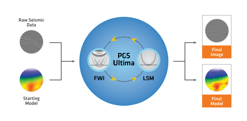
PGS Ultima is a game-changing realization of several decades of industry ambition. It is a move away from traditional sequential processing to a simultaneous inversion combining velocity model building and least-squares imaging.
The main advantage of PGS Ultima is that an accurate velocity model and reflectivity image can be derived faster, as the simultaneous inversion resolves both using the same raw seismic data as input. Most time-consuming processing steps in a seismic sequence can be bypassed allowing a significant turnaround time reduction in imaging projects by more than 50%.
A key technical aspect of PGS Ultima (Figure 1) is the absence of leakage between parameters, so both products of the simultaneous inversion are not contaminated by each other, unlike many current industry approaches. Another differentiator is the implementation of a single modeling engine allowing the full wavefield to be modeled including reflections, multiples, refractions and diving waves.
PGS Ultima provides companies with more time to analyze their data and therefore reduce their risk in field exploration, development or production.
Simultaneous Inversion Speeds up Processing and Delivers Reliable Products
Traditional cascaded imaging workflows take time. Full waveform inversion (FWI) is normally run at the beginning of a processing sequence using raw data and has become the main tool for velocity model building. Least-squares migration (LSM) requires an accurate velocity model and fully preprocessed data, so it happens at the end of the preprocessing sequence and after the velocity model building stage. When applications rely on the products of earlier steps we end up with time-consuming cascaded workflows.
The simultaneous nature of PGS Ultima means FWI and LSM are now performed in a single framework. It uses raw seismic data, models the full acoustic wavefield, and outputs accurate velocity models and reliable reflectivity.
Suitable for Use on Any Data
PGS Ultima can be used on any data, streamer or OBS. There are no limitations on acquisition geometries to get accurate and deep models, as the code uses the entire wavefield, reflections, multiples, refractions, diving waves and turning waves.
A Different Approach to a Long-standing Problem
PGS Ultima uses a unique implementation of scale separation, so there is no parameter leakage, and the velocity model and reflectivity are not contaminated by each other. This is unique in the industry and is achieved with a robust imaging condition that performs the scale separation and hence removes completely the leakage between these two parameters in the multi-parameter inversion. Another key implementation is the vector reflectivity modeling engine allowing the entire wavefield to be modeled and reducing the need for long offset acquisition.
Save Time with PGS Ultima
Only limited processing is needed for PGS Ultima, the input required is a starting velocity model and raw gathers. This means time is saved on preprocessing steps like designature, deghosting and demultiple. By doing the inversion for velocity and reflectivity simultaneously not only does this save time but it can deliver an even better image.
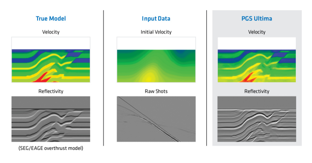
Synthetic Tests Validate PGS Ultima
A modified version of the SEG/EAGE overthrust model is used to demonstrate the benefits of the simultaneous inversion. The true velocity and reflectivity models are shown below in the left column (Figure 2). A heavily smoothed velocity field is used as a starting model along with raw gathers (middle column). The results of the simultaneous inversion are shown in the right column. The inverted velocity correctly retrieves the detailed features in the velocity model. Similarly, the inverted reflectivity is equivalent to the true one.
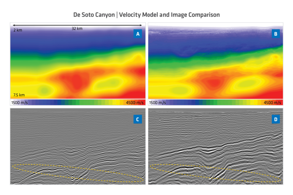
Field data example from the Gulf of Mexico
The field data example in Figure 3 is from the deepwater Gulf of Mexico, De Soto Canyon area. The data is multisensor GeoStreamer with a maximum offset of 12 km. The input shot gathers were not muted and the full wavefield was used for the inversion. Figure 3a shows the initial velocity model while Figure 3c displays the reflectivity from the first iteration of the inversion, which is equivalent to RTM image using the starting velocity model. Since the data contained multiples, crosstalk artifacts are observed in the RTM image and are indicated by the yellow oval. The results after several iterations of simultaneous inversion using PGS Ultima are shown in Figures 3b and 3d. The inverted models clearly display higher resolution, better balanced amplitude and a reduction of the crosstalk in the final reflectivity model.
Future Vision
PGS has the ambition to leverage PGS Ultima to reduce project turnaround by at least 50% over today’s standards. Whilst PGS Ultima is available on projects today, the technology will continue to be developed with the intention to:
- Extension to include pre-stack gather output;
- Include update of the anisotropic terms within the inversion; and
- Validate amplitude fidelity giving confidence when inverting for rock properties.
Recommended Reading

Comstock, Aethon’s 17 Western Haynesville Wildcats Make 112 Bcf to Date
2024-08-01 - Comstock Resources and Aethon Energy each added one well to Texas state production data on the new western Haynesville play, dubbed ‘The Waynesville.’ The oldest has surfaced 2.1 Bcf per 1,000 lateral ft to date.

EOG Testing 700-ft Spacing in Ohio’s Utica Oil Window, Sees Success
2024-08-05 - EOG Resources’ test at the northern end of its 140-mile-long north-south leasehold produced IPs similar to those from a nearby pad.

Where, When and How to Refrac—Weighing All the Options
2024-07-12 - Experts weigh in on strategic considerations when deciding how to rejuvenate production from a tired well.

In Ohio’s Utica Shale, Oil Wildcatters Are at Home
2024-08-23 - The state was a fast-follower in launching the U.S. and world oil industry, and millions of barrels of economic oil are still being found there today.

The OGInterview: BPX E-fracs Push ‘Values Up, Emissions Down,’ CEO Says
2024-07-02 - BPX Energy CEO Kyle Koontz discusses the company’s role as the “nimble entrepreneurial” arm of supermajor BP in the Permian Basin and Haynesville and Eagle Ford shales.
Comments
Add new comment
This conversation is moderated according to Hart Energy community rules. Please read the rules before joining the discussion. If you’re experiencing any technical problems, please contact our customer care team.