The need for optimal wellbore placement to maximize recoverable reserves is a given, and engineers have always harnessed the available technologies to do this. However, the technologies have fallen short of the optimum, impacting productivity and profitability. RockSense provides at-bit bed boundary identification, giving engineers real-time information about a formation boundary at the point of transition. The technology turns the theory of mechanical specific energy (MSE) into practice. This article reviews what this new technology can achieve in practice using two historical datasets, both based on the availability of conventional logs from adjacent wellbores for corroboration.
The first dataset is from a coiled tubing (CT) drilled sidetrack of a well in a densely drilled site in North America. No horizontal wells had been drilled in the area previously, and the objective was to increase production through increased reservoir contact.
The operator used 3-D seismic to evaluate the formations and identified a subsurface ridge that could be acting as a trap. The well path was planned to pass about 4.5 m (15 ft) below the formation top and track the formation by holding inclination. The oil-water contact was believed to be 12 m (40 ft) below the formation top and, if entered, would significantly impact the well economics. Gamma ray sensors were used for depth correlation because relying on seismic depth alone would not provide the accuracy required. The hole section was drilled using a single phase fluid in the build section.
Running RockSense on the data gathered during this job revealed compelling similarity in the shape of the density logs and the RockSense trace when plotting porosity against true vertical depth (TVD) (Figure 1).
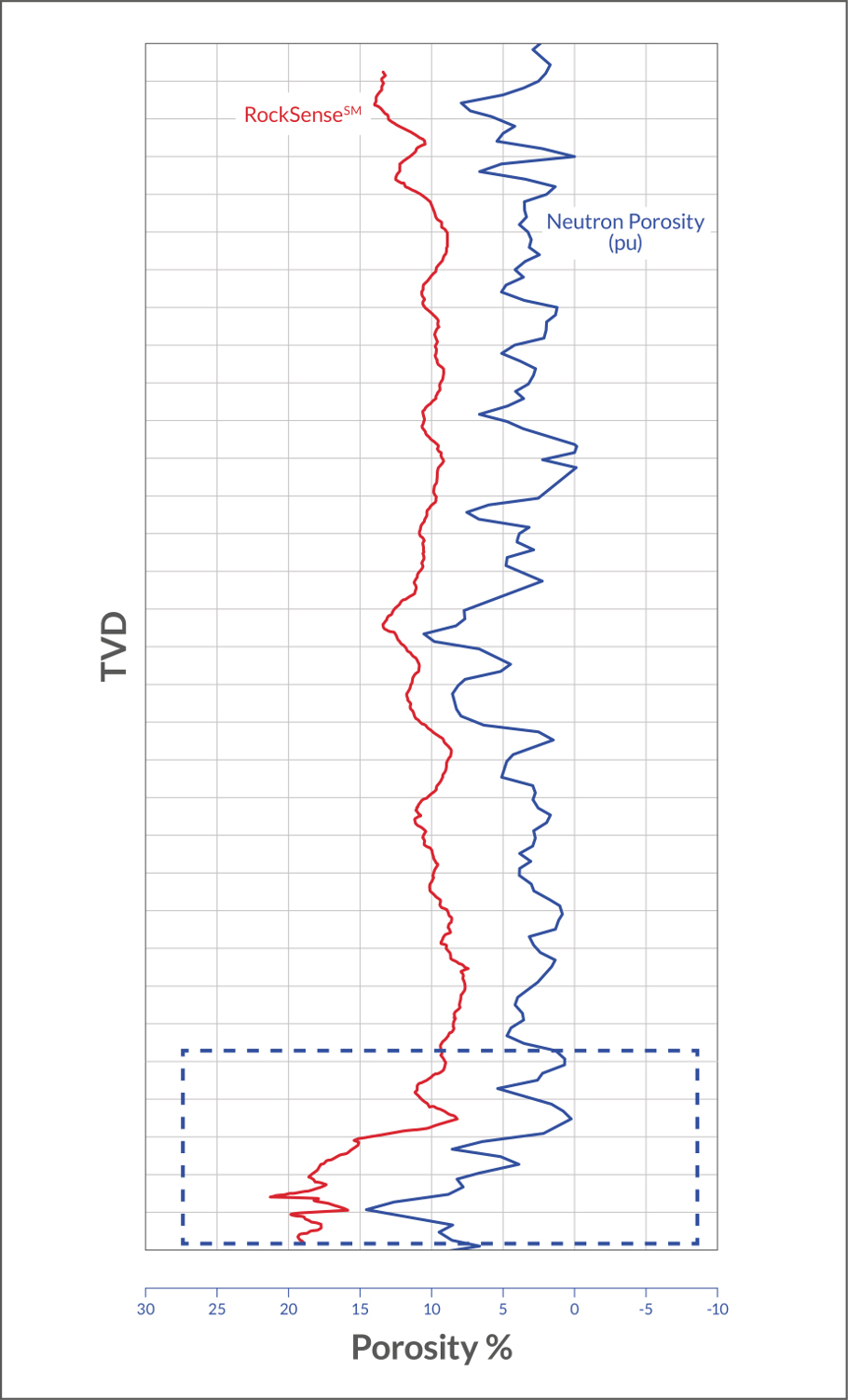
FIGURE 1. A compelling similarity between the shape of the density log for nearby wells and the RockSense log when plotting both quantities against TVD is shown. (Note the RockSense scale is offset in this view.) (Source: AnTech Ltd.)
The second dataset involves underbalanced CT drilling in a shale gas well in the U.S. (Figure 2). In this instance, a 4¾-in. lateral was drilled using a mixture of up to 40% nitrogen to minimize formation damage. The aim was for the wellbore to stay within an identified formation layer. Processing the historical data using RockSense identified substantial footage drilled below the target formation. If the technology had been used in real time, a more reactive steering strategy could have been followed to avoid exiting the formation.
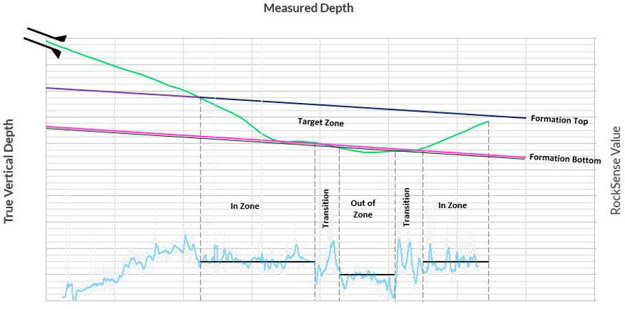
FIGURE 2. Applying RockSense historically reveals its sensitivity to boundary crossings. (Source: AnTech Ltd.)
Operation
MSE is the energy required to drill a length of the hole in a formation, which reveals the composition of the formation. As the drillability of the formation changes, so does the energy required to drill it. Although the theory had the potential to revolutionize drilling accuracy, the technology available until now has meant the practical application has been limited. This is because calculating MSE accurately requires real-time measurement of downhole weight on bit (WOB) and torque.
Historically, these were derived from surface measurements, with empirical corrections applied to the effects of buoyancy and friction. However, the noise of the corrections was almost always louder than the MSE signal changes caused by differing formation characteristics. More recently, technology advances have made downhole measurement of WOB and torque possible, but mud pulse bandwidth limitations have imposed severe constraints on the definition that can be achieved.
The latest generation of CT drilling bottomhole assemblies (BHAs) features integrated downhole sensors and high-speed wired telemetry to provide a technology platform that finally makes high-definition MSE measurements possible.
It works by measuring the power input to the motor as the hole is being drilled to gain an understanding of the type of rock being drilled. The technology measures differential pressure and flow rate. With knowledge of principal operating constants for the motor, an expression for power regarding pressure and flow rate can be written. This power is integrated as the hole progresses, giving a value of energy expended per foot of hole drilled and therefore giving a relative indicator of the changes in formation.
By continually monitoring torque, WOB, pressure and ROP, RockSense provides information about the formation being drilled in real time. Further, because wired telemetry has a high data rate, multiple measurements can be made for every foot drilled, and operators can gain inch level resolution. It opens a new window on the downhole environment as drilling progresses.
Considering the advantages
In the absence of the ability to accurately measure MSE, two geosteering methods have traditionally been used. The first method uses sensors measuring factors such as gamma, resistivity and porosity. Although these sensors are mature, reliable and consistent, the position of the sensor along the BHA is a significant drawback. The drillbit sits at the bottom of the BHA, but the directional sensor package sits perhaps 6 m to 7 m (20 ft to 25 ft) farther back, behind the mud motor. A change in formation characteristics is not evident until the bit is 6 m to 7 m farther into the formation. Even if there is no productivity impact, the time spent drilling unproductive formation impacts the project’s bottom line.
The second method for geosteering is by cuttings analysis. However, the time taken to circulate cuttings to surface, capture them and prepare them for analysis inevitably means a delay. Once again, the formation of interest is penetrated before confirmation is received at the surface, reducing the TVD available to complete a steering action. Dispersion of cuttings in the annulus (different sizes and densities travel at different speeds) also can adversely affect depth resolution.
Both methods undoubtedly represented the best available solution for their time, but both are superseded by the technology now available.
With RockSense, at-bit bed boundary identification is possible for the first time. The information is delivered in real time and because the data are representative of conditions at the bit—not behind it—the driller can deliver an optimally placed wellbore with more meters drilled in the target zone. The result is improved lifetime productivity, higher IP and substantially improved project economics.
Recommended Reading

Exxon’s Payara Hits 220,000 bbl/d Ceiling in Just Three Months
2024-02-05 - ExxonMobil Corp.’s third development offshore Guyana in the Stabroek Block — the Payara project— reached its nameplate production capacity of 220,000 bbl/d in January 2024, less than three months after commencing production and ahead of schedule.

Venture Global, Grain LNG Ink Deal to Provide LNG to UK
2024-02-05 - Under the agreement, Venture Global will have the ability to access 3 million tonnes per annum of LNG storage and regasification capacity at the Isle of Grain LNG terminal.

What's Affecting Oil Prices This Week? (Feb. 5, 2024)
2024-02-05 - Stratas Advisors says the U.S.’ response (so far) to the recent attack on U.S. troops has been measured without direct confrontation of Iran, which reduces the possibility of oil flows being disrupted.

McKinsey: US Output Hinges on E&P Capital Discipline, Permian Well Trends
2024-02-07 - U.S. oil production reached record levels to close out 2023. But the future of U.S. output hinges on E&P capital discipline and well-productivity trends in the Permian Basin, according to McKinsey & Co.

EIA: Oil Prices Could Move Up as Global Tensions Threaten Crude Supply
2024-02-07 - Geopolitical tensions in the Middle East and ongoing risks that threaten global supply have experts questioning where oil prices will move next.