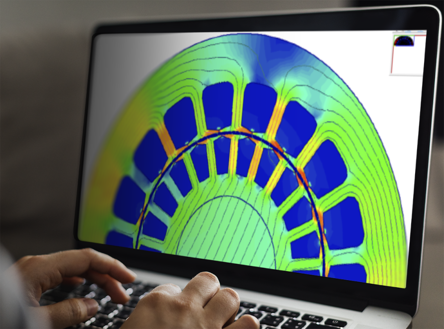
A finite element analysis validated the lamination magnetic design of the Apergy AFFIRMED PowerFit motor. The design successfully generated more than 200 hp from a small-diameter motor. (Source: Apergy)
[Editor's note: This story originally appeared in the April 2020 edition of E&P. Subscribe to the magazine here.]
Operators active in unconventional shale plays have increasingly shifted to drilling and completing wells with 5½ inch, 20-lb and 23-lb casing. These smallerdiameter wells cost significantly less to drill and complete, but more importantly, they offer greater wellbore stability and protection against the frac forces from adjacent wells on a pad. But smaller wellbores present challenges when the assets are passed over to the production teams.
A large percentage of shale wells require electric submersible pumping (ESP) systems to recover the higher fluid volumes that are common early in the production cycle. However, traditional ESP equipment was not designed to operate effectively in deeper wells with long laterals and completed with 5½-inch, 20-lb and 23-lb casing.
To achieve the necessary horsepower to lift fluids from 7,000 ft or more, operators traditionally have had two options: ESPs with a 4.56-inch outside diameter (OD) motor or ESPs with a triple-tandem 3.75-inch OD motor. Neither choice is ideal for a variety of reasons.
Challenges for ESP systems
ESP systems with 4.56-inch OD motors provide the required horsepower to produce the desired production rates from deeper wells, and they can be installed in smaller-diameter, heavy-wall casing, but this requires modifications to the motor. The lock plates, or antirotation devices, that keep the motor head and base from unthreading from the main housing must be removed to fit in 5½-inch, 20-lb casing. This modification introduces substantial risks to the mechanical integrity of the motor. And even after removing the lock plates, 4.56-inch OD motors can get stuck in the well, particularly if there are any deviations in the wellbore trajectory.
Also, these larger motors are often “turned down,” which means the housing is reduced from a 4.56-inch OD to up to a 4.40-inch OD by shaving material from the housing. This modification causes significant reliability concerns because the compression on the motor’s stator lamination stack is relaxed, which can result in spinning laminations and an electrical short. Even without the lock plates and material shaved from the housing, 4.56-inch motors will not fit in 5½-inch, 23-lb casing.
Another concern with 4.56-inch OD motors in 5½-inch, 20-lb casing is fluid velocity. Tighter clearances between the motor and the casing cause the fluid velocity to increase. If the fluid flow rate is below 2,000 bbl/d, there is no issue, but higher flow rates, which are common early in the life of an unconventional well, create fluid velocities that can result in erosion of the motor’s metallurgy.
The other traditional ESP option to produce wells completed with 5½-inch, 23-lb casing is 3.75-inch OD motors. With this option, operators are forced to make a choice between production and equipment run life. It takes a triple-tandem, 3.75-inch configuration—or three motors connected together—to get even close to the same horsepower rating of one 4.56-inch OD motor. As a result, production rates are compromised.
Often, operators will “push” 3.75-inch OD motors beyond their safe operating limits in an effort to generate more horsepower and, therefore, more production, but this practice introduces serious reliability concerns. Also, the additional connections between motors with a triple-tandem configuration also create greater potential for electrical shorts.
Fluid velocity is not as much of a concern with 3.75-inch motors, but the fluid velocity can be too low in some cases. Adequate fluid flow past the motor is required to prevent overheating.
Permanent magnet motors
In recent years, operators have been experimenting with permanent magnet motors (PMMs), which are available in smaller diameters, but that option comes with its own set of issues. PMMs require a special surface control system to monitor and adjust the downhole ESP system operation, so operators can’t use their existing surface equipment. The surface control system accounts for 50% or more of the total cost of an ESP, making systems using a PMM a costly option.
Plus, PMMs introduce a significant safety risk versus standard ESP motors. When an ESP shuts down, there is typically backspin in the pump until the fluid column reaches a point of equalization. For typical ESP systems, this is not an issue because standard induction motors create very low voltage during backspin. However, due to the magnets in the motor rotors, PMMs essentially become a generator during backspin, creating lethal voltages that pose a significant danger to field personnel.
Based on the limitations of all the existing ESP options, it is no surprise that shale operators have been seeking a better solution for slimline unconventional wells—one that does not require a trade-off between space in the wellbore and horsepower and does not jeopardize the reliability of the system.
Meeting small-diameter challenges
Late in 2018, the Apergy UNBRIDLED ESP systems motor engineering team initiated a project to design and build a submersible induction motor to meet the challenges of small-diameter unconventional wells. The goal was to create a motor that provides the same horsepower as 4.56-inch motors but with a smaller-diameter housing that allows adequate clearance in 5½-inch, 20-lb and 23-lb casing.
The Apergy AFFIRMED PowerFit motor features an optimized electromagnetic design that delivers more than 200 hp from one motor while also delivering better efficiency as production rates decline and limiting motor winding temperature rise.
The smaller size of the motor eliminates the need to modify equipment and mitigates potential erosive wear from extreme fluid velocity up to 4,500 bbl/d. The motor size also leaves room in the wellbore to install tech wires for sensors below the motor and run chemical injection capillary tubing to the base of the motor. This is an important feature because scale buildup is a major issue for equipment installed in many shale wells. The motor design features
- Optimized rotor-shaped bars to maximize horsepower output; properly allocated tooth width balances electric loading versus magnetic loading;
- Parallel stator tooth to ensure uniform flux density;
- Balanced sizing of the stator slot area versus stator teeth to balance electric loading versus magnetic loading;
- Generous stator back iron to prevent excessive flux density, which reduces iron loss/heat in the stator OD region; a good thermal circuit efficiently conducts heat out of the motor, keeping the stator OD cooler to extend motor life; and
- Successful saturation of stator and rotor bridges to eliminate flux leakage and increase power output.
After the motor design was completed, the team conducted extensive testing in the Apergy motor dyno apparatus to validate the model based on IEEE 114 and IEEE 252 standards. The testing criteria included a no-load test to measure fluid and friction loss, core loss and steel saturation; a voltage variation/load variation to measure optimal voltage versus load; a performance test to quantify horsepower output, speed, torque, power input, efficiency and power factor; and a temperature rise test to measure the average motor winding temperature. The laboratory tests validated the parameters outlined in the motor model. These include 208 hp, 82.5% efficient from 100% to 50% loaded and 400 F maximum motor operating temperature.
Following testing, Apergy conducted 10 field trials, primarily in 5½-inch, 23-lb casing, which is the most challenging application. Nearly all the trials used tandem motors to generate more than 400 hp. When the motor was commercially launched in January 2020, the field trials had achieved more than 2,000 days of run time with zero issues related to motor operation.
Recommended Reading

E&P Highlights: April 8, 2024
2024-04-08 - Here’s a roundup of the latest E&P headlines, including new contract awards and a product launch.

Exclusive: Carbo Sees Strong Future Amid Changing Energy Landscape
2024-03-15 - As Carbo Ceramics celebrates its 45th anniversary as a solutions provider, Senior Vice President Max Nikolaev details the company's five year plan and how it is handling the changing energy landscape in this Hart Energy Exclusive.
ShearFRAC, Drill2Frac, Corva Collaborating on Fracs
2024-03-05 - Collaboration aims to standardize decision-making for frac operations.

The Need for Speed in Oil, Gas Operations
2024-03-22 - NobleAI uses “science-based AI” to improve operator decision making and speed up oil and gas developments.
Chevron Hunts Upside for Oil Recovery, D&C Savings with Permian Pilots
2024-02-06 - New techniques and technologies being piloted by Chevron in the Permian Basin are improving drilling and completed cycle times. Executives at the California-based major hope to eventually improve overall resource recovery from its shale portfolio.