[Editor's note: A version of this story appears in the September 2020 edition of E&P Plus. Subscribe to the magazine here.]
For operators developing shale reserves, determining an optimal infill well strategy can be technically challenging and plagued by multiple sources of uncertainty. Even under the best circumstances, multiple reservoir properties combine to create a complex blend of matrix permeability, natural faults and fractures, and landing interval properties that make ideal placement highly variable from pad to pad—especially within stacked reservoirs.
While heterogeneity in the reservoir cannot be controlled, multiple strategies have been created to mitigate the risk of placing infill wells close enough for negative fracture interactions, instances where overlapping stimulated areas between wells undermines the economic value of one or both assets. These mitigation techniques almost exclusively focus on preventing fracture linkage, either by limiting fracture growth or by controlling the direction of propagation.

In cases where parent well production has significantly depleted the reservoir, stimulation of infill wells frequently results in a higher degree of asymmetric fracture growth, with fractures propagating toward depleted and previously fractured zones surrounding the parent well rather than stimulating previously unexploited reserves. An optimal mitigation strategy redirects the energy of hydraulic fracturing toward more even fracture growth and a more distributed, rather than longer, fracture itself. Yet the selection of an optimal mitigation strategy is not clear cut, particularly when individual pads deal with unique heterogeneities and natural fracture outlays.
To this end, diagnostic tools provide significant value in determining which completion strategy and the possible combination of mitigation techniques best align with an operator’s technical needs and economic drivers. A Permian Basin operator evaluated the effectiveness of far-field diverters at controlling fracture growth and limiting interwell communication between child and parent wells. Liquid chemical tracers were used to establish and quantify flow from and between wells and determine if a novel diversion strategy was preventing negative fracture interference.
Building a Tracer Test of Far-Field Diverters
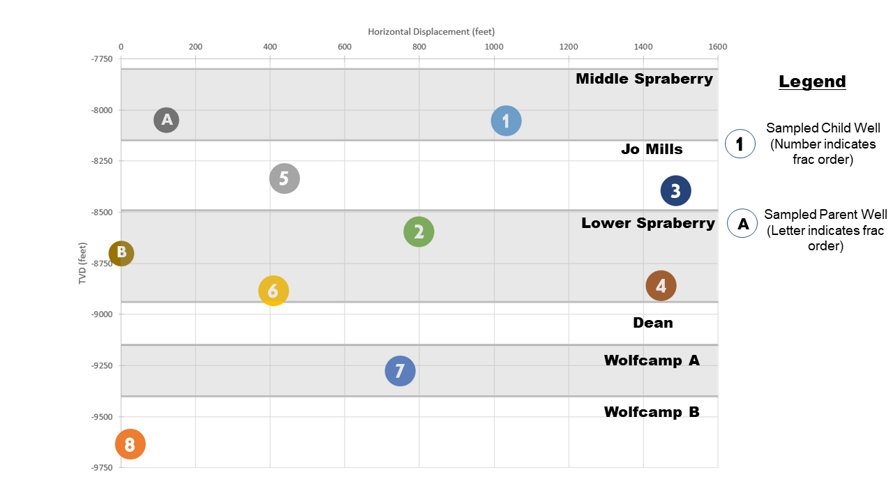
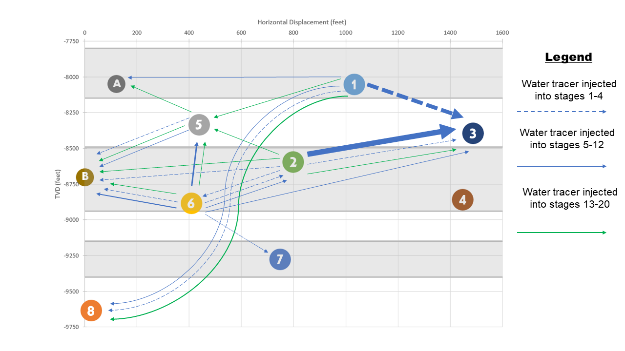
A tracer study was constructed around 10 horizontal wells in the Spraberry trend. Eight of these wells were newly hydraulically fractured infill wells, grouped into two pads and spread across the Middle and Lower Spraberry, Wolfcamp A and B, and the Jo Mill intervals. Two nearby parent wells also were monitored for possible interwell communication with the child wells. Figures 1 and 2 provide a reference for the relative placement of all 10 wells.
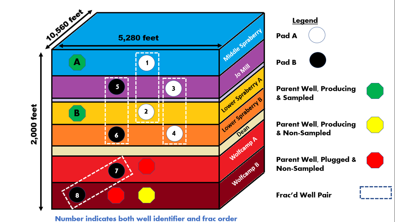
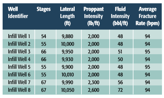
Each infill well was completed in a manner typical for the area; a slickwater stimulation program, using a combination of 100 mesh and 40/70 sand, was used to zipper frac well pairs. Table 1 provides a summary of the stimulation program used for the infill wells.
To compare the use of far-field diverters against a baseline stimulation, Wells 1, 2, 5 and 6 were divided into four treatment zones. In the case of these four wells, stages 1-4 were treated with both a liquid oil and water tracer but no diverter to provide verification of flow from the toe of the well. Stages 5-12 were treated with a second oil and water tracer pair but again no diverter. Stages 13-20 were treated with a third unique oil and water tracer pair alongside a far-field diverter. The remainder of the lateral did not see the use of tracers or diverters. In the case of child wells 3, 4, 7 and 8, the first 20 stages were treated with liquid water tracers, liquid oil tracers and diverter.
To further protect the parent wells from negative fracture interactions, Parent Wells A and B were shut in for a period of time to restore the depletion zone surrounding them prior to fracturing the child wells. Parent Well A also saw an injection of water to prepressurize the near wellbore area and provide additional protection from child fracture growth into its drainage area. Three additional parent wells exist within the Wolfcamp A/B and in proximity to Well 7, but these wells could not be sampled over the course of the study. However, the depletion effects of these three parent wells are expected to affect fracture growth direction during the stimulation of the child wells.
Over the span of 200 days, samples were collected from the eight child and two parent wells and analyzed for the presence of the injected tracers. When tracers were recovered from the same well that saw their injection, the combination of tracer concentration and production history generated a mass balance that revealed how much of the oil and water production came from each of the three treated zones. When a tracer was discovered in the production fluid of an offset well, its presence evidenced an intermingling of stimulated reservoir volumes (SRVs) that allowed for tracer migration to occur.
Study Results
Establishing diverter effectiveness was centered on the tracer behavior of Wells 1, 2, 5 and 6. These four wells placed zones treated with diverter alongside untreated zones, allowing the effects of diversion to be compared to a baseline established by the same well. Heat maps are provided in Figure 3, showing the migration of water tracers among the sampled wells. Compare the heat map distribution of stages 1-4 and stages 5-12; for the two zones that did not see diverter use, tracer migration trends are largely identical. The variations that do exist are relatively small, such as the worst of the interwell communication occurring between wells 1 and 3 for the toe-most stages and between Wells 2 and 3 for stages 5-12. Given that Wells 1 and 2 are a zippered pair, this is not a meaningful distinction.
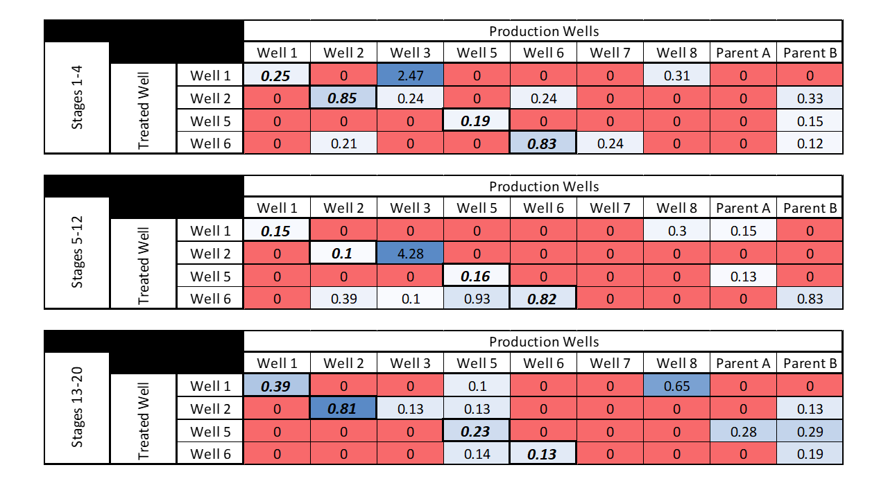
For Well 6, interwell communication favors its nearest offset—Well 5—for stages 1-4 and switches to its next nearest offset well—Well 7—for stages 5-12. Where communication with a parent well occurs, it nearly universally occurs with Parent Well B that was not prepressurized. Where diverters were used, there is definitive and measurable change in the growth of the fracture network surrounding the child wells. Diversion successfully restrains the high overlap in the stimulated area surrounding the Well 1 and Well 2 pair and Well 3. In place of strong growth in an easterly direction, a more symmetric network grows to both the east and west of the zippered well pair. However, due to the closeness of well spacing, this substitutes strong communication with Well 3 with less extreme, but still problematic, communication with Wells 3 and 5.
Diversion did not prove effective in preventing fracture network growth toward depleted zones within the reservoir. Though tracer results are suggestive that diverter use may increase cluster efficiency and provide a more even distribution of fracture fluid through each perforation during fracturing, the improvement was insufficient to significantly change the likelihood of negative fracture interactions (Figure 4).
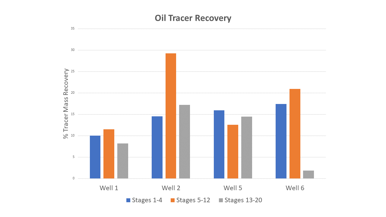
An analysis of the oil tracers suggests other trade-offs might exist when using this particular diverter. Where diverted stages could be compared to non-diverted stages, it was often observed that the non-diverted stages had higher or comparable recovery of injected oil tracers (Figure 5). Since the mass recovery of oil tracer is an effective proxy for oil production from these zones, the recovery rates raise concerns that the diverter has a near-field effect that is negatively effecting oil production from the treated well.
In fracturing infill Wells 1 and 2 first, the operator attempted to create a pressure barrier that prevented fracture growth from Wells 3 and 4 to preferentially grow toward either the depleted parent wells or the newly drilled wells of Pad 2. Once Pad 2 was in turn stimulated, Wells 5 and 6 were stimulated first in the hopes that energy reserved in the reservoir post-fracturing would also shield the remaining wells from the stress effects originating in the depletion zone. Managing stimulation order did prove effective in mitigating negative fracture interactions for the remaining child wells in this study; the tracer behavior of Wells 3, 4, 7 and 8 illustrated very low levels of tracer migration and only to the nearest offset wells. Communication with the two depleted parents was essentially eliminated.
Conclusion
The use of liquid chemical tracers allowed for a rapid, cost-effective method to evaluate far-field diverters within the Spraberry trend. In using these markers to trace interwell oil and water movement, it was observed that without diverters, the planned stimulation program generated a far-field fracture system, meaning these stage fractures had an extended connection to the reservoir, which overlapped the SRV of its neighboring offsets.
In stages where far-field diverters were used, asymmetrical growth of this far-field fracture system was curtailed but introduced new problems. In creating a more even fracture network around child wells, the use of diverters ensured that negative fracture interactions occurred more often but with slightly diminished magnitude. The use of diverters also notably penalized oil production. Where well spacing was increased or frac order could be managed, the operator achieved comparable or better mitigation of overlapping SRVs and so the future use of diversion was abandoned for their Spraberry field development.
Recommended Reading

NOG Closes Utica Shale, Delaware Basin Acquisitions
2024-02-05 - Northern Oil and Gas’ Utica deal marks the entry of the non-op E&P in the shale play while it’s Delaware Basin acquisition extends its footprint in the Permian.

Vital Energy Again Ups Interest in Acquired Permian Assets
2024-02-06 - Vital Energy added even more working interests in Permian Basin assets acquired from Henry Energy LP last year at a purchase price discounted versus recent deals, an analyst said.

California Resources Corp., Aera Energy to Combine in $2.1B Merger
2024-02-07 - The announced combination between California Resources and Aera Energy comes one year after Exxon and Shell closed the sale of Aera to a German asset manager for $4 billion.

DXP Enterprises Buys Water Service Company Kappe Associates
2024-02-06 - DXP Enterprise’s purchase of Kappe, a water and wastewater company, adds scale to DXP’s national water management profile.

Tellurian Exploring Sale of Upstream Haynesville Shale Assets
2024-02-06 - Tellurian, which in November raised doubts about its ability to continue as a going concern, said cash from a divestiture would be used to pay off debt and finance the company’s Driftwood LNG project.