In many oil reservoirs, the ultimate recovery can be improved through the injection of water for both pressure support and flood of the reservoir to sweep residual oil toward the producer wells. The injected water must be distributed uniformly into the reservoir structure to generate effective sweep. Reservoir heterogeneity, faults and fractures and frictional pressure losses lead to inefficient sweep, bypassed oil and early water breakthrough into production wells.
Injection control devices (ICDs) can provide a cost-effective means of effectively distributing flow. Deployed as part of the lower completion or retrofitted into an existing well, the lower completion is segmented into multiple zones or compartments with one or more devices per zone.
The ICDs provide a flow restriction across the completion creating a pressure drop as a function of the flow rate into the zone. The relationship between rate and pressure drop can be engineered by changing the size or quantity of the ICDs to limit injection into high permeability zones and increase injection into low permeability zones. Thereby flow distribution is achieved. For some applications, with a correctly designed completion, this technology has been proven to be highly effective in improving injection distribution.
To effectively manage flow distribution in a reservoir with highly conductive fractures, it is necessary to deploy highly restrictive ICDs in the compartments containing the fractures to accommodate the large injectivity contrast between the reservoir pore structure. The challenge for both production and injection application with ICDs is the detection and identification of such fractures during reservoir characterization and logging of the wellbore before installation of the completion.
ICDs are fixed designs and once installed cannot be adjusted, except through well interventions in the case where sliding sleeves also are used. An additional challenge in water injection applications is dynamic changes in the reservoir due to the injected water process.
These include
• Fracture propagation due to hydraulic pressure;
• Thermal fracturing due to the injection of cold water to the relatively hot reservoir;
• Formation impairment due to the injection of solids, oil in water, shale swelling or bacterial responses;
• Any unexpected variations in fluid responses; and
• Existing ICD technology can only accommodate these changes using highly restrictive settings throughout the completion. However, the high-resultant pressure loss can have a significant impact on the topsides requirements and does not offer a practical solution.
In response to the challenges of effective water injection in dynamically and naturally fractured reservoirs, Tendeka has developed a reactive or autonomous ICD technology that adjusts without intervention to a more restrictive setting when fractures or other reservoir features create thief zones. This allows the optimum setting to be maintained for both injections into the pore spaces and for effective fracture control while retaining the cost-effective benefits of ICD and the robustness of this technology for life-of-well operations.
The FloFuse system achieves this effect using a dual ICD setup (Figure 1).
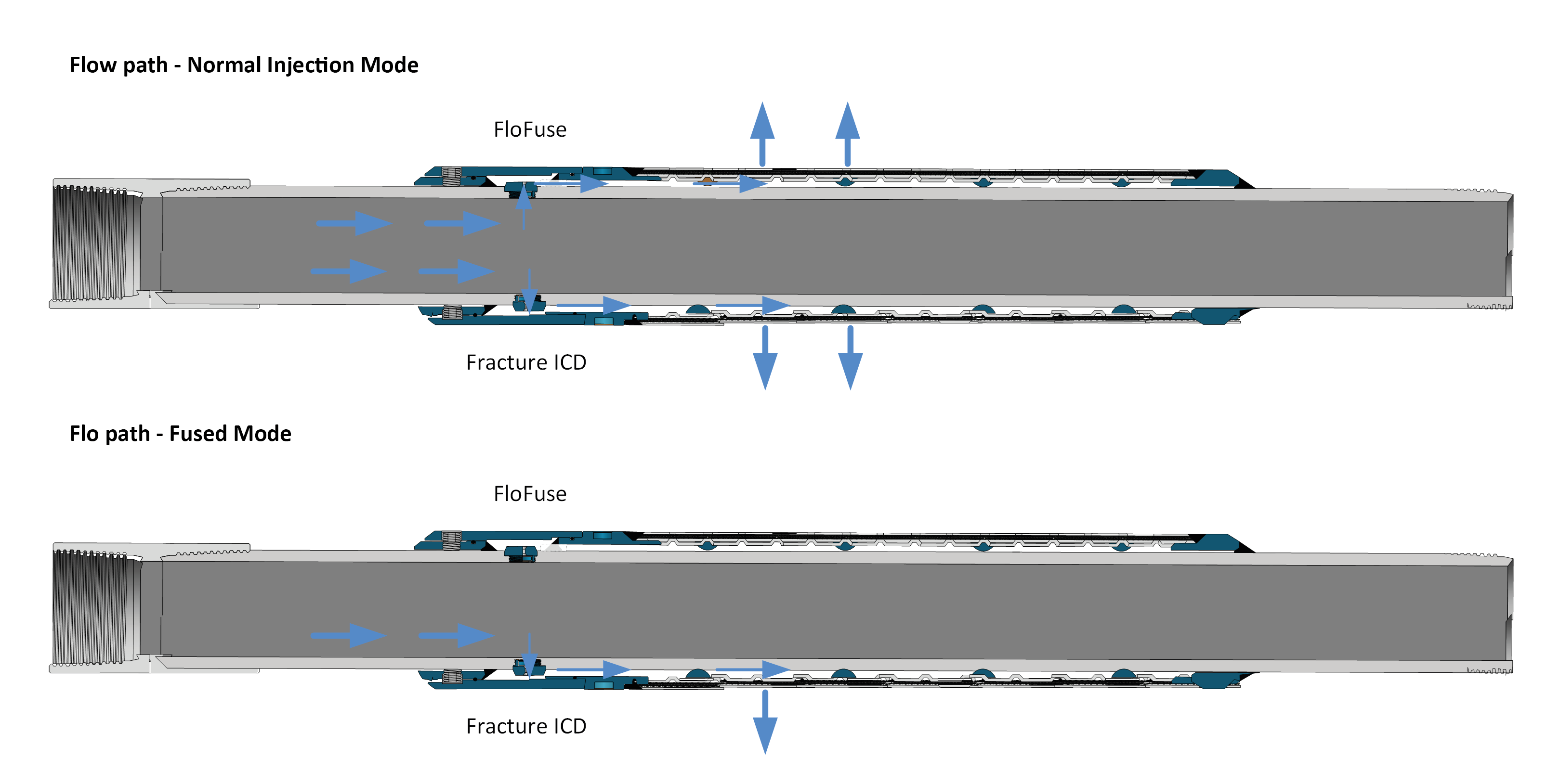
The ICDs are mounted into the completion base pipe, in this example a sand control screen. Injected water passes through the ICDs into a housing mounted at one of the screens, through the housing to the underside of the screen section and then out into the annulus between the screen and formation. In normal injection mode, the ICD setting is the combination of the flow area of the FloFuse itself and the “Fracture ICD,” which is simply a highly restrictive ICD nozzle. When the flow conditions are reached to activate the FloFuse, this device closes and the injection is restricted by the smaller resultant flow area of the fracture ICD alone.
Figure 2 shows the performance of the FloFuse System in more detail.
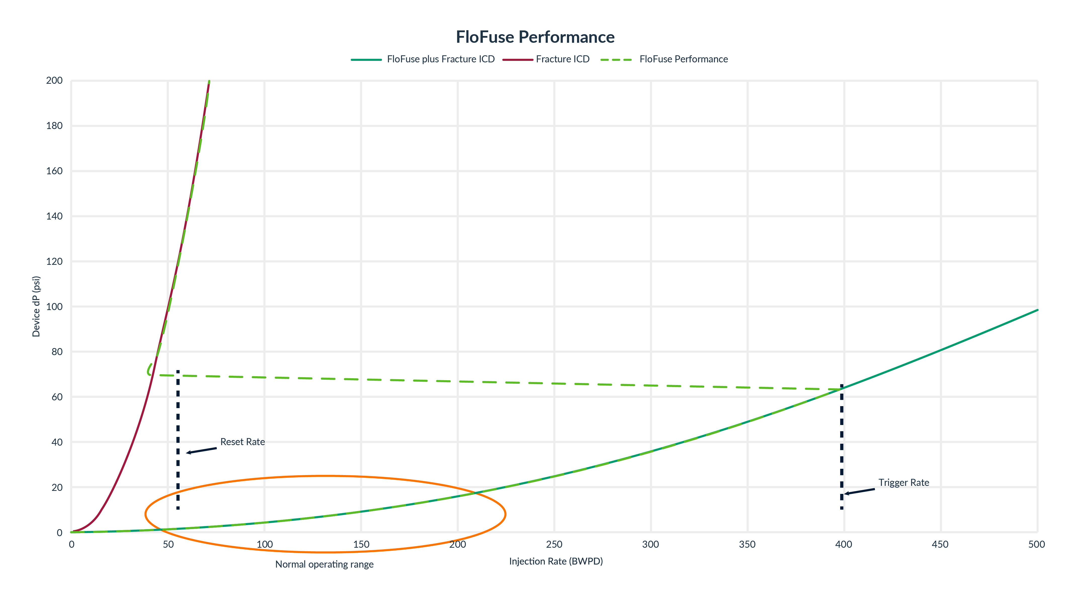
In application, the completion is designed so that effective conformance into the matrix or pore structure can be achieved in the “normal operating range” with the combined flow area of the FloFuse and Fracture ICD. If a fracture is encountered, which causes the flow rate to increase, the FloFuse will trigger to provide a more restrictive setting for effective control of flow into the fracture.
The valve remains dynamically reactive and will reopen if distributed flow can be achieved. The dynamic and reversible operation of the valve makes it suitable for applications where the permeability contrasts change over time, such as in thermally fractured water injection wells and where matrix stimulation is used to improve near-wellbore permeability.
Have a story idea for Tech Watch? This feature highlights leading-edge technology that has the potential to eventually address real-life upstream challenges. Submit your story ideas to Group Managing Editor Jo Ann Davy at jdavy@hartenergy.com.