Seismic processing, imaging, characterization and interpretation activities are preferably executed as a continuous workflow to maintain seismic data integrity and consistency, as the workflow progresses from raw field data to the respective deliverables. Geophysicists are tasked with constructing a workflow from hundreds of applications and algorithms, as well as thousands of parameters, to achieve desired project outcomes. Almost all these applications and algorithms are based on assumptions about the underlying geological (earth) model complexity and subsurface conditions.
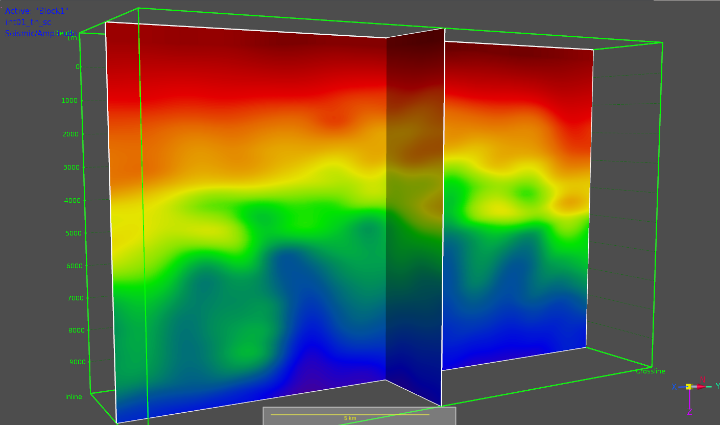
Many of these applications require an explicit representation of an earth model composed of a geologic structure and velocity properties. These applications operate on and update an initial reference or background velocity model using algorithms and objective functions that relate seismic measurements to the model parameters. When properly parameterized, the updated model and associated seismic deliverables generated from that model can be a significant step toward ensuring that project objectives are met.
The updated velocity model establishes a framework for the generation of other models (facies, reservoir property, pore pressure and discrete fracture network) that are required for geologic targeting and well planning. These properties are often strongly associated with the modeled velocity parameters. Consequently, co-location of geophysical and geologic properties becomes important.
A better understanding of the dependencies of seismic velocities on the full earth model description is needed. The transition from time to depth operations for seismic imaging and inversion requires a parameter transformation from effective (average) to formation (interval) properties. Furthermore, anisotropic velocity models, needed to describe the dependency of seismic velocity on the direction of wave propagation, depend heavily on the structure, layering and fracture network of geologic formations. Consequently, accurate parameterization of the velocity model is highly dependent on a richly described geologic model.
Despite this strong dependency of velocity parameters on the earth model, velocity modeling is frequently carried out independently of geologic model construction. This is largely because building a velocity model consistent with the structure, stratigraphy, facies and lithology of the earth model is not simple. It requires the synchronization of two generally large systems, one for the determination of velocity models using the seismic method and the other for the generation of geologic models from many sources of data. The synchronization of these models will ensure the following:
Respective constraint (invariants) are honored in both systems. For the geophysical (velocity) model, the invariants are the recorded travel times. For the geologic model, constraints can include all well data, sequential stratigraphic rules, erosion rules, fault type and behavior, and intraformational chronostratigraphic behavior. Honoring the invariants of one system forms a complementary check and balance on the other.
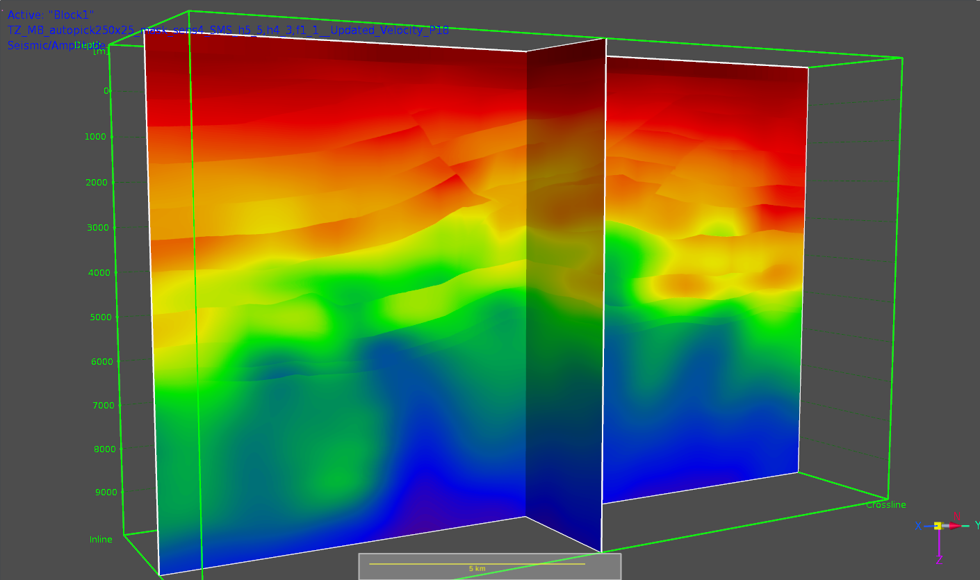
Model updates are concurrent and automatic. The development of a geologically constrained velocity model requires numerous iterations of seismic reflection tomography, with continuous updating of structure and properties of the model. This process needs to be automated and engineered into the respective geophysical and geologic applications. In practice, the geometry measurements (dip and azimuth) extracted from the layer boundaries of the volumetric earth model are transferred to the seismic tomography system. After the tomographic update, velocity parameters and displacements (XYZ) are returned to the geomodeling system where the model is automatically rebuilt. This process ensures that the respective models remain convergent and that seismic properties and geologic grids remain co-located.
Velocity operations conform to the geology. Velocity processes, such as smoothing and geostatistical operations, must be allowed to follow the structural model and stratigraphic layers that describe the model to avoid the creation of nonplausible velocity distributions. Seismic inversion operators also can be designed to follow the stratigraphic layers of the model.
All data are honored. Models are sealed. Seismic imaging in areas of strong deformation or intrusions (salt and basalt), requires that this structural complexity be accurately represented. All faults need to be fully described with no approximations or deformations. Salt-horizon and fault-horizon interfaces need to be properly handled so they do not create leakages in the velocity model. Intrusions need to be sealed. Models should be initiated in a sealed state and remain sealed during the tomographic update process described previously.
Model integrity can be continuously tested. Seismic interpretation is a key step in the velocity model building process, subject to continuous refinement. Interpretation uncertainty, introduced by extensive faulting or lack of image clarity, can introduce additional uncertainties within the seismic imaging, velocity modeling and geomodeling loop. Seismic interpretation data can be evaluated and corrected in chronostratigraphic space, where inconsistencies between the seismic data and the chronostratigraphically transformed model become apparent.
Velocity model uncertainties
Following all the best practices outlined does not leave geophysicists and geomodelers entirely in the clear. The acquisition sampling of seismic data is generally incomplete and imperfect, leaving practitioners with velocity model uncertainties caused by undersampling. In mathematical terms, this causes the tomography solution to be over-determined, as there are more unknown parameters than known. This means that multiple velocity models can fit the observed seismic data (i.e., a range of velocity models can flatten the reflectors in prestack common image gathers).
To evaluate this uncertainty, a tomographic approach can be introduced that preserves the seismic travel times. In this method, the parameters of the background or reference velocity model can change while the travel times of all ray pairs are preserved. Perturbations can be applied to all types of model parameters. The travel times of all ray pairs traced during the tomographic inversion are the kinematic invariants referenced earlier. In the migrated domain, all the kinematically equivalent models should provide more or less flat reflection events within the common image gathers.
When significant and systematic mis-ties between interpreted seismic depth horizons and well markers exist, well-marker mis-tie tomography can be used to obtain modifications to the vertical velocity or Thompsen anisotropic delta parameters to minimize the mis-ties. This form of tomography is a global, geophysically robust and interpretation-friendly approach for assessing depth uncertainty when planning or drilling horizontal wells. It is particularly relevant in shale plays, where decisions need to be made quickly and staying within thin target lithozones is challenging.
Velocity model uncertainty can originate from many sources; however, it is best evaluated using both geophysical and geologic modeling systems that can incorporate all available data.
The need for geologically constrained velocity and property models derived from the seismic method begins with an understanding of the impact it can have on exploration and field development programs. The practice of integrating the models should be more pervasive and should be invoked from the onset of a seismic program.
Recommended Reading

BP’s Kate Thomson Promoted to CFO, Joins Board
2024-02-05 - Before becoming BP’s interim CFO in September 2023, Kate Thomson served as senior vice president of finance for production and operations.

BP Pursues ‘25-by-‘25’ Target to Amp Up LNG Production
2024-02-15 - BP wants to boost its LNG portfolio to 25 mtpa by 2025 under a plan dubbed “25-by-25,” upping its portfolio by 9% compared to 2023, CEO Murray Auchincloss said during the company’s webcast with analysts.

TPG Adds Lebovitz as Head of Infrastructure for Climate Investing Platform
2024-02-07 - TPG Rise Climate was launched in 2021 to make investments across asset classes in climate solutions globally.

Sherrill to Lead HEP’s Low Carbon Solutions Division
2024-02-06 - Richard Sherill will serve as president of Howard Energy Partners’ low carbon solutions division, while also serving on Talos Energy’s board.

Magnolia Appoints David Khani to Board
2024-02-08 - David Khani’s appointment to Magnolia Oil & Gas’ board as an independent director brings the board’s size to eight members.