As applications for coiled tubing (CT) advance, CT simulation software must keep up the pace if field personnel are to plan and execute operations safely, efficiently and predictably. However, when software models are built with unverifiable data inputs and little to no field feedback, the resulting simulations lack accuracy, take too long and cannot be easily updated as field conditions change.
Since the inception of its first-generation CT modeling software three decades ago, Baker Hughes, a GE company (BHGE), has continued to develop innovations as field operations require. The CIRCA Pro software system now includes a comprehensive set of tools to simulate, model, plan and execute complex CT operations in deeper and more tortuous well geometries.
This article charts the evolution of the CT modeling software from its earliest days to the developments that will be required in the coming years. A field case illustrates how the software improves CT intervention with minimal nonproductive time (NPT).
Flow analysis
The earliest iteration of CT modeling software focused on developing a deeper understanding of downhole flows and pressures during CT operations. The CT flow model was developed from multiphase rheological and frictional correlations obtained from laboratory flow loop testing and validated against field data.
The model predicts flow rates and pressures under various flow configurations, including normal circulation with flow down the CT work string and up the completion as well as circulation in the reverse direction. The system also can determine if circulation is even possible or whether the current job design will simply result in lost returns.
Typical flow analysis output includes hydrostatic and friction pressure gradients; pressure, temperature, density and velocity for each phase; gas volume fraction/ foam quality, effective viscosity and shear rate; Reynolds number; and flow type for two-phase flow regimes.
Tubing force analysis
Deploying CT strings in deeper and geometrically complex wellbores requires an understanding of the forces that cause deformational changes like buckling or collapse.
Therefore, the CT modeling software was expanded to include tubing force analysis (TFA). This model considers the well geometry, mechanical friction, CT size, shape and material strength to predict the onset of stability changes.
The TFA output at various measured depths downhole includes contact friction force, triaxial stress, spiral pitch, elastic stretch, collapse differential limits and buckling equilibrium. At the wellhead, TFA output includes the weight indicator gauge reading at the operating limit, the maximum load that can be applied to the bottomhole assembly (BHA), time to failure if the BHA becomes stuck, the differential collapse pressure and triaxial stress along the CT work string, and the reel-back tension required to spool the CT.
Debris cleanout
Using CT to help remove debris during a well cleanout is more complicated than simply finding a critical velocity that can completely fluidize and move cuttings. Some try to model this based on Stokes’ theorem with modifications by Taylor. However, neither of these applies because the flow is not static nor in an infinite medium. Using empirical curve fits to laboratory data, the CT modeling software was further refined to perform solids transport analysis for better planning and execution of the cleanout process.
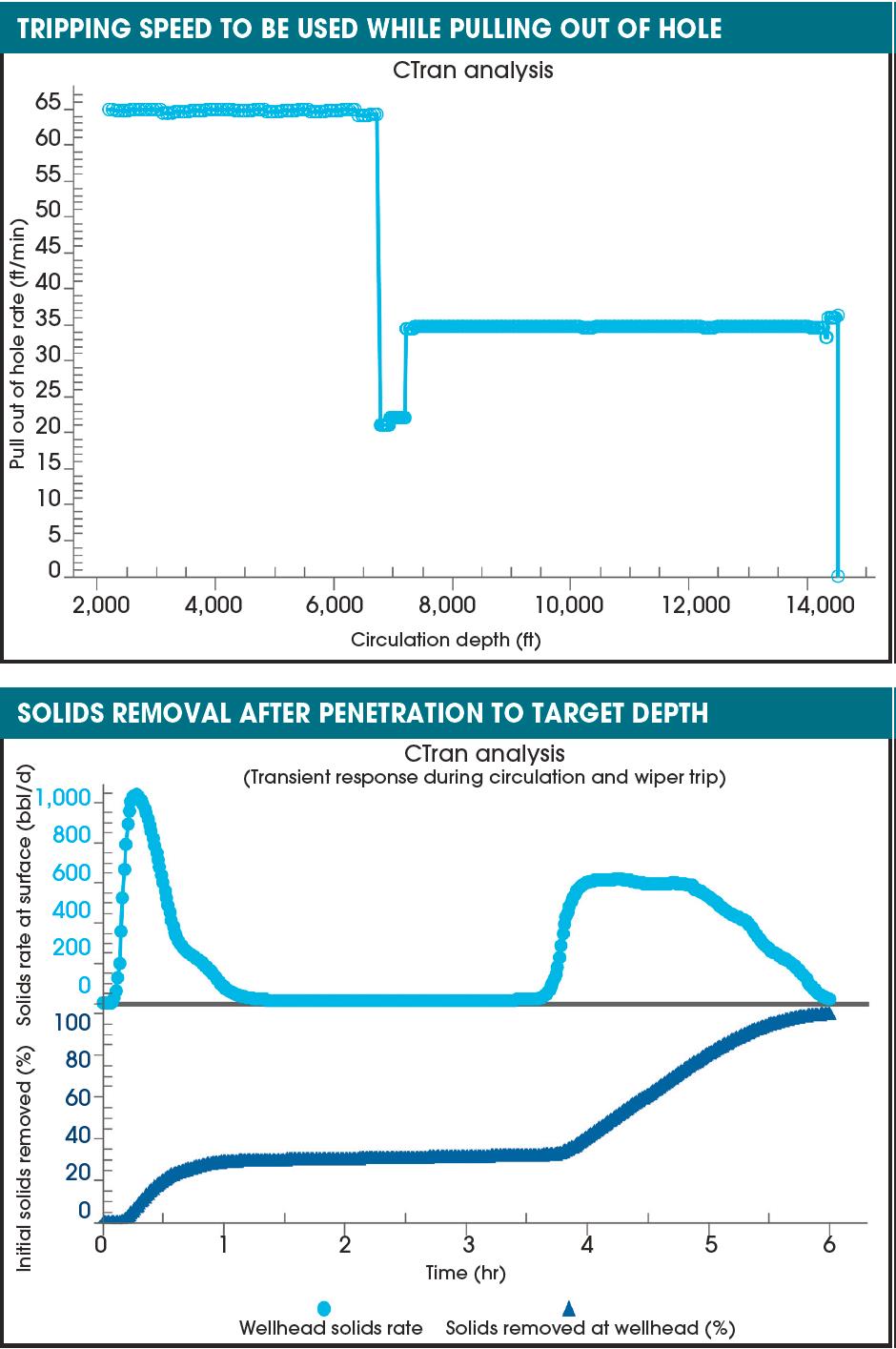
This analysis can be run with various cleanout fluids and solid types. The penetration rate, circulation time and wiper trip rates can be varied along with the flow rates to optimize a cleanout.
The analysis output includes the total time and fluid volumes required, solids rate at surface and recommended wiper trip rates, distribution of solids along the wellbore during cleanout and total estimated volume of solids that can be removed.
From steady-state to transient
Steady-state models remain the most common and simplest CT simulation approach. But in practice, the downhole conditions during many CT operations are transient. Consequently, the steady-state models have been extended to account for downhole transient effects at the preplanning and execution stages of CT operations.
The transient analysis enables running an infinite number of changes and events to a scenario that was previously run under steady-state flow, TFA and solids-transport assumptions. The transient analysis remaps the steadystate analysis variables into a finite volume mesh. Well conditions can be recorded at any time during the transient run as a snapshot. Selecting multiple snapshots permits the engineer to observe the complete data results at multiple points in time.
Events are available that allow the user to change the CT speed, the choke size at the surface equipment, the transient run time and the flowing rates of injected and produced liquids and gases. Additional liquids and gases can be introduced to the transient analysis at any time during the simulation.
Proven in the field
CT models uploaded into a field application can automatically run in the background during the job. The model is updated with real-time field data to obtain a more accurate picture of the operation and stay ahead of potential problems.
BHGE’s CT modeling software has modeled, planned and executed solids transport in more than 30,000 wells to date. In one field operation, the service provider was directed to use a field consultant’s pump rate values to mill out 50 plugs in a recently perforated 3,658-m (12,000-ft) South Texas well.
Carrying the plug debris to the surface would require a proper balance of fluid volumes, pump rates and tripping speeds. However, the consultant’s CT cleanout standard operating procedure used outdated guidelines, which delivered pump rates and tripping speeds the service provider suspected were not adequate for the job.
The field-supplied fluid volume, pump rate and tripping speed were inputted into the CIRCA Pro modeling software. The software confirmed higher pump rates and slower tripping speeds were required to perform a full cleanout without sticking the BHA.
However, the field consultant insisted the values from the standard operating procedure be used. But while pulling out of the hole after milling out all plugs, the CT became stuck. Operations were shut down for two days to free the BHA.
A review of the job revealed the standard operating procedure’s pump rates and tripping speeds were inadequate. The operator realized the value of the solids transport analysis in the modeling software and assigned all future millout planning to the CT service provider. Subsequent millout jobs were delivered without incident, and the operator saved money by avoiding NPT and eliminating intervention/ fishing runs.
Future developments
This modeling software puts the knowledge of CT experts into the hands of those who do not have that background. Following the downturn, the industry’s shortage of experienced field engineers has made the use of such software more critical than ever for increasing the efficiency, compliance and safety of CT operations.
Future CT workflow advances will focus on driving automation in several key areas, including prejob modeling and real-time operational feedback. The use of intelligent injector controls will help increase service delivery certainty by actively intervening and automatically maintaining safe CT operating limits at all times.
The next steps in CT interventions will incorporate control systems with telemetry systems to trip the CT to a specific depth and automatically slow it down for known obstructions or well profile changes.
These automation advances will ultimately streamline CT operations, saving time and money in the process. Fewer operational decisions will be left exclusively to the surface personnel, and well-trained technicians will be able to operate the equipment with input from remote experts.
Recommended Reading
Hess Corp. Boosts Bakken Output, Drilling Ahead of Chevron Merger
2024-01-31 - Hess Corp. increased its drilling activity and output from the Bakken play of North Dakota during the fourth quarter, the E&P reported in its latest earnings.
The OGInterview: Petrie Partners a Big Deal Among Investment Banks
2024-02-01 - In this OGInterview, Hart Energy's Chris Mathews sat down with Petrie Partners—perhaps not the biggest or flashiest investment bank around, but after over two decades, the firm has been around the block more than most.

Some Payne, But Mostly Gain for H&P in Q4 2023
2024-01-31 - Helmerich & Payne’s revenue grew internationally and in North America but declined in the Gulf of Mexico compared to the previous quarter.
Petrie Partners: A Small Wonder
2024-02-01 - Petrie Partners may not be the biggest or flashiest investment bank on the block, but after over two decades, its executives have been around the block more than most.

BP’s Kate Thomson Promoted to CFO, Joins Board
2024-02-05 - Before becoming BP’s interim CFO in September 2023, Kate Thomson served as senior vice president of finance for production and operations.