
(Source: TechnipFMC group)
[Editor's note: A version of this story appears in the August 2020 edition of E&P. Subscribe to the magazine here.]
Accelerating the understanding of the industry’s carbon footprint and the corresponding cost implications are critical to understanding how businesses can collaborate to reduce carbon emissions and meet global climate initiatives.
Cost and carbon footprint justify the green energy transition initiative, but stakeholders expect data behind statements and actions. After all, what cannot be measured cannot be managed.
To develop a sustainable execution model, the TechnipFMC group recently conducted a carbon footprint analysis within the scope of an engineering study of an offshore floating wind project to analyze elements for minimizing carbon emissions. The purpose of this early-stage study of an industrial project is to examine how the engineering, procurement, construction and installation (EPCI) phase can reduce its carbon footprint. Offshore floating wind will create far less emissions as an electricity provider than other fossil-based energy resources; hence, material use is significant, so it is worth examining how this may be minimized.
This principle of considering where carbon reduction savings could be realized is therefore applicable to any project, carbon intensive or not.
Carbon footprint of a floating wind installation
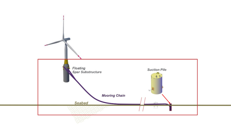
The scope of the study is therefore the complete system hardware with the exception of the tower, turbines, blades and electrical cables. Items included in the scope are within the boundary of the red box in Figure 1. The 11-off spar is anchored with three mooring lines each, which are secured in a grid of 19 suction anchors.
Procurement, construction and installation
Bottom sections of the concrete spar substructures will be slip-formed in the dry dock before being completed at an inshore deepwater fabrication site at about 330 ft water depth. Upon completion of the concrete works, steel components (e.g., flanges, fittings, boat landing deck and J-tubes) will be mounted onto the substructure. Assembly of the tower, nozzle and blades will be performed at a specially prepared separate site using a shore crane.
The mooring system and suction anchors will be preinstalled at an offshore site. Upon completion of inshore assembly operations, the complete structure will be towed away and connected to anchor chains. The final phase of installation activities includes laying, connection and protection of electrical cables. The carbon footprint analysis also covers marine operations executed during inshore assembly, namely towing activities between the dry dock, deepwater slip-forming site and tower assembly location.
The carbon footprint analysis also covers marine operations executed during inshore assembly,
namely towing activities between the dry dock, deepwater slip-forming site and tower assembly location.
CO₂e emission assessment
When measuring carbon emissions, the common approach is to convert main greenhouse gases into equivalent tonnes of CO₂e by using the Greenhouse Gas Protocol.
Within the emission assessment, each material has an emission factor that is multiplied with the amount in each case. Standard factors may be used or, alternatively, third-party verified emission factors can be applied if suppliers are able to provide an Environmental Product Declaration. For the purpose of this study, concrete and some steel suppliers were able to provide specific emission factors lower than the common European standard values. This emphasizes the importance of close cooperation with key suppliers.
Defining the boundaries of measurement is a critical aspect of measuring carbon footprint. This case examines upstream and direct emissions. For a full carbon footprint evaluation, it is also necessary to include downstream emissions, such as the end-of-life aspects of the wind turbine system elements, as this might affect final results. An executed analysis is seen as a first step in acquiring required knowledge and enhancing environmental awareness. The next step would be an assessment of commercial aspects and a cost-benefit analyses of carbon reduction initiatives.
The most significant parameters affecting the carbon footprint in the order of ranking are found to be steel components (e.g., mooring chains, suction anchors, auxiliary equipment), emissions from transportation and installation vessels, reinforced concrete (e.g., concrete substructure and rebar steel) and solid ballast.

Materials account for the largest footprint, whereas the transport has a smaller share. In addition, a sensitivity analysis was selected driven by engineering logic and project execution boundaries. With regard to the material selection of the spar, both concrete and steel substructures were evaluated (Figure 2). The pie charts show that substituting the concrete substructure material with steel nearly doubles the total project carbon footprint by 93%. As for the concrete case, there is an option of a more environmentally friendly concrete. The environmentally friendly concrete reduces CO₂e emissions attributed to reinforced concrete by 25% for an insignificant premium. This environmentally friendly concrete is included in the 16% in Figure 2.
Keeping in mind that all elements apart from the floating substructure are kept the same, attention is needed when looking at percentages only. The mooring elements in both scenarios of the pie charts in Figure 2 are the same numbers; however, they appear to be different because only relative percentages are presented. Note, the only differentiating factor in Figure 2’s pie charts is the spar/floating substructure’s material. In any case, it is evident that the amount of steel or material is the prominent factor in determining the carbon footprint. Chains proved to a significant share of the total scope included. In certain cases, segments of the steel mooring lines could be substituted with polyester ropes, which could result in achieving cost and CO₂ reductions.
Glass-refined plastic instead of steel was analyzed as an alternative.
This proved to reduce carbon emissions by half.
Glass-refined plastic instead of steel was analyzed as an alternative. This proved to reduce carbon emissions by half. Relatively speaking, considering the low share of the total scope, this reduction is small. However, due to the size of the project and absolute numbers, the savings are not insignificant.
Project awareness of carbon footprint
The carbon footprint measurements proved to be interesting and eyeopening to the team members. The results would have been impossible to predict beforehand. Moreover, the findings would not have been realized through engineering calculations alone. Engagement from the project team and stakeholders proved to be essential. Project execution aiming for reducing carbon emissions should therefore include awareness campaigns, building of alliances and, at the very least, an acknowledgment that it is a learning journey.
To account for the risk that some large emission factors are left outside of defined study boundaries, the team suggested an alliance type coordination with the operator and main suppliers. The idea was to establish a “project within the project” to identify and prioritize cross-company green initiatives.
In this regard, the energy industry can look to the construction industry as a model. For a long time, the latter has focused on toxic materials as well as energy consumption and waste as
it relates to climate change risk and material depletion.
To achieve efficient resource utilization, a theory states it is necessary to move beyond linear reasoning within familiar boundaries by applying an experimental mindset and acting in alliances when responding to complex sustainability challenges. That certainly proved to be true in this study.
Acknowledgment:
This article is based on the OTC-30561-MS paper, “A Carbon Footprint Evaluation Method for Offshore Floating Wind Installations.”
Recommended Reading

Biden Administration Criticized for Limits to Arctic Oil, Gas Drilling
2024-04-19 - The Bureau of Land Management is limiting new oil and gas leasing in the Arctic and also shut down a road proposal for industrial mining purposes.

Exclusive: The Politics, Realities and Benefits of Natural Gas
2024-04-19 - Replacing just 5% of coal-fired power plants with U.S. LNG — even at average methane and greenhouse-gas emissions intensity — could reduce energy sector emissions by 30% globally, says Chris Treanor, PAGE Coalition executive director.

FERC Again Approves TC Energy Pipeline Expansion in Northwest US
2024-04-19 - The Federal Energy Regulatory Commission shot down opposition by environmental groups and states to stay TC Energy’s $75 million project.

US Orders Most Companies to Wind Down Operations in Venezuela by May
2024-04-17 - The U.S. Office of Foreign Assets Control issued a new license related to Venezuela that gives companies until the end of May to wind down operations following a lack of progress on national elections.