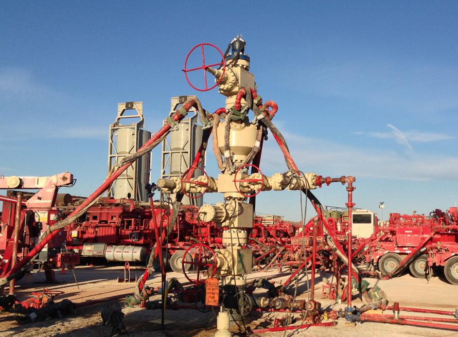
A better understanding of downhole mechanics has allowed operators to increase fracturing stage lengths through the use of diverters. (Source: FreezeFrames/Shutterstock.com)
[Editor's note: A version of this story appears in the August 2020 edition of E&P. It was originally published Aug. 3, 2020. Subscribe to the magazine here.]
Diverters have been used in the industry for decades, and the justification for using diverters is clear—to improve cluster efficiency. However, they have yet to become a mainstay in most completion designs. One of the main reasons that diversion has not been more widely adopted is inconsistency in diversion results. In most cases, operators see pressure responses at their wellbore that seem to indicate that diversion is occurring when the diverters are placed.
However, these responses are often inconsistent and can vary by thousands of psi and, in the worst cases, cause costly screenouts. Consequently, production improvements are often inconsistent at best, and at worst, they might result in even poorer well productivity than wells that did not have diverters applied.
If one accepts the commonly held belief that in plug-and-perf completions not all clusters are stimulated equally when multiple clusters are treated simultaneously—a belief that has been proven by multiple methods including microseismic monitoring, distributed acoustic sensing (DAS)/ distributed temperature sensing from fiber optics and tracer data—then it should be clear that a single diversion design may not be applicable for every fracturing stage within a wellbore.
For example, a stage in which there is very low heterogeneity in rock strength may have most clusters taking similar fluid volumes right from the start of pumping, while another stage with high heterogeneity may only have half of the initial clusters taking fluid. In this example, these two stages have very different diversion requirements. In the first case, the diverter may shut off active clusters prematurely, causing the clusters that take fluid after diversion to be overstimulated. While in the alternate case, the diverter may effectively divert fluid into clusters that might otherwise be under-stimulated. In this effect, fluid was initially effectively distributed to five of six clusters, but only two clusters were taking fluid after diversion. As a result, there were two overstimulated and four under- stimulated clusters.
Engineered diversion
This understanding of why most diversion applications have inconsistent results has led to the development of engineered diversion. Similar to the concept of engineered completion designs where perforation clusters are put into “like rock” so each cluster will break down at similar pressures, engineered diversion uses the rock properties along the lateral (along with advanced perforation modeling and design) to control how and when clusters take fluid during the diversion.
Engineered diversion design starts with the basic concept that clusters should be divided into groups of primary and secondary (and in some cases tertiary) clusters, and each of these groups should be stimulated discretely. That is to say, the goal is to have the primary, and only the primary clusters, take fluid initially. Then the diverter is dropped to completely block off these primary clusters, which then opens up the secondary clusters for treatment. This important basis of design allows precise control of when and how much diverter needs to be dropped.
For example, if six of 10 clusters are grouped as primary, and four of 10 are secondary, then the diverter would ideally be dropped after 60% of the fluid is pumped. Then enough diverter would be dropped to block those six clusters, followed by the remaining 40% of the treatment. This discretization of the clusters is what allows engineers to better predict and control fluid movements.
For an engineered diversion design to be effective, there needs to be a way to predict and control which clusters take fluid and when.
There are two key elements to this:
- Calculate the breakdown pressures of each perforation cluster; then
- Calculate the bottomhole pressures (BHPs) during the fracture treatment.
If one can make accurate estimates of these two numbers, they can ensure that when stimulating the primary clusters, the bottomhole treating pressure never exceeds the breakdown pressure of the secondary clusters.
While the calculation of BHP is relatively straightforward, the calculation of breakdown pressure can be a touch more complex. There needs to be some measurement of mechanical properties along the lateral. Traditionally, these data might have been obtained from sonic log runs, but due to the cost and operational complexity of obtaining these logs, this is often not a practical solution. Another option is to use drilling data to infer mechanical properties of the rock being drilled through, a process that has been applied on thousands of wells over the last several years.
The amount of energy required to drill through a unit of rock is known as the mechanical specific energy (MSE) and is made up of two parts: the drilling efficiency and the compressive strength of the rock. If the drilling efficiency is normalized, the result is directly representative of the compressive strength of the rock being drilled. This value is often referred to as the RockMSE and can be used to infer the breakdown pressure of the formation along the lateral.
Once the breakdown pressures are established, then perforation clusters can be placed with primary perforation clusters being put in sections of the stage with the lowest breakdown pressure and secondary clusters being put in sections of the stage with the highest breakdown pressure. At this point, a near-wellbore fluid distribution model needs to be created. Varying perforation designs are tested until an optimized design is obtained, wherein there is enough perforation friction created to distribute fluid among all the primary clusters, yet not so much as to exceed the breakdown pressures of the secondary clusters.
Evaluating diverter effectiveness
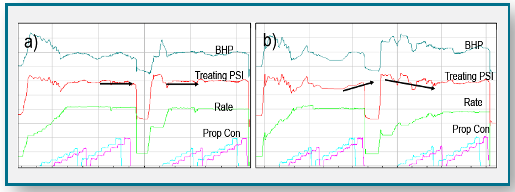
A quick way to evaluate the effectiveness of the diversion design is to review the pressure data during pumping. Due to the discretization of the perforation clusters, there should be two indicators of effectiveness in the pressure data. When the diverter initially hits the perforation clusters, there should be a clear increase in pressure.
At that point, the fluid should start entering the secondary perforation clusters. As a result, there should be a change in the pressure slope as new fractures are being created and the net pressure is essentially reset” (Figure 1). Using these two methods of evaluation, several hundred fracture stages have been evaluated. It was found that when lateral measurements and near-wellbore modeling were used to design the diverter strategies, more than 90% of stages had effective diversion. In contrast, stages that used geometric perforations and a consistent diversion schedule only showed effective diversion in 60% of stages.
Thus, with a thorough understanding of downhole mechanics and an accurate estimation of rock mechanical properties and heterogeneity along the lateral, it has been shown the effectiveness of diverters can be significantly increased. This understanding has allowed operators to increase fracturing stage lengths through the use of diverters, which can lead to a significant reduction in completion costs without having an adverse effect on production.
Recommended Reading
EIA: Permian, Bakken Associated Gas Growth Pressures NatGas Producers
2024-04-18 - Near-record associated gas volumes from U.S. oil basins continue to put pressure on dry gas producers, which are curtailing output and cutting rigs.

Benchmark Closes Anadarko Deal, Hunts for More M&A
2024-04-17 - Benchmark Energy II closed a $145 million acquisition of western Anadarko Basin assets—and the company is hunting for more low-decline, mature assets to acquire.

‘Monster’ Gas: Aethon’s 16,000-foot Dive in Haynesville West
2024-04-09 - Aethon Energy’s COO described challenges in the far western Haynesville stepout, while other operators opened their books on the latest in the legacy Haynesville at Hart Energy’s DUG GAS+ Conference and Expo in Shreveport, Louisiana.

Mighty Midland Still Beckons Dealmakers
2024-04-05 - The Midland Basin is the center of U.S. oil drilling activity. But only those with the biggest balance sheets can afford to buy in the basin's core, following a historic consolidation trend.

Mesa III Reloads in Haynesville with Mineral, Royalty Acquisition
2024-04-03 - After Mesa II sold its Haynesville Shale portfolio to Franco-Nevada for $125 million late last year, Mesa Royalties III is jumping back into Louisiana and East Texas, as well as the Permian Basin.