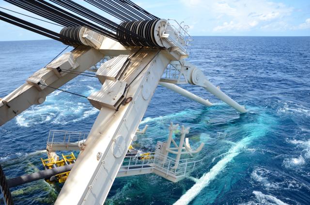
S-lay pipeline installation can be performed in water depths of 3,000 m or more, depending on the suspended weight of the pipeline. (Source: NickEyes/AdobeStock)
Pipelines are critical components of oil and gas production. As the industry advances into increasingly complex subsea landscapes and more remote areas, considerations around pipelaying capabilities have become more important.
But what is the most economically efficient pipeline design and lay capability within the industry today? In short, it is determined by three key factors: the pipelaying method, the characteristics of the pipe and the pipelay vessel itself.
Critical factors
Pipeline installation methods, pipe diameter and wall thickness selection set limitations as to what water depth a pipeline can be laid. The design methodology adopted for deepwater pipeline systems is normally based on the wall thickness and material grade selection that meets the maximum allowable bending strain experienced during installation, often specified by the pipeline operator.
Installation in deeper water requires particular consideration to the lay vessel capabilities, which can influence pipeline design in itself. The vessel should have enough tension capacity for supporting the pipeline in the deepest waters and be able to maintain station using a tight dynamic positioning system.
This understanding is based on intermediate and deepwater experience, where in most cases the barge thrust is insensitive to wall thickness selection, and tension requirements are often adequately within vessel capabilities. However, for selected pipeline examples, analytical results show that, at any given water depth, the impact of the specified strain limit on top tension is not significant. Yet, the fuel cost for station keeping and maintaining the lay tension to prevent buckling is. Fuel consumption is increased in water depths of greater than 1,500 m (4,921 ft), which can significantly impact costs.
Pipelaying capabilities
To understand how pipe design impacts economics, it is crucial to understand the pipelay methods employed in deep water today. The two main methods used to install pipeline in deep water are S-lay and J-lay.
When performing S-lay pipeline installation, the pipe is eased off the stern of the vessel as the boat moves forward. The pipe curves downward from the stern over a large radius curved structure referred to as a “stinger” and through the water until it reaches the “touchdown point,” or its final destination on the seafloor. As more pipe is welded in the firing line and eased over the stinger to the seabed, the pipe forms the shape of an “S” in the water.
The stinger, measuring up to 91 m (300 ft) or more in length, extends from the stern to support the pipe as it is moved into the water as well as controls the curvature of the pipe during installation. The pipelay vessels typically used in deep water have adjustable stingers, which can be shortened or lengthened according to the water depth.
Maintaining the required tension during pipeline installation using the S-lay process is achieved via a series of tensioners and a controlled forward thrust of the vessel, keeping the pipe in a controlled catenary and preventing it from buckling.
With current equipment, S-lay can be performed in water depths of 3,000 m (10,000 ft) or more, depending on the suspended weight of the pipeline, and laying as much as 6 km (4 miles) or more per day can be archived. The maximum depth at which a given pipeline can be laid could be increased with a longer stinger of the lay barge and bigger vessel tension capacity. However, choosing these options may require increasing the capability of the dynamic positioning system
or employing the support of tugs to maintain position and to aid forward movement. A longer stinger would be subjected to greater hydrodynamic forces, and the higher tension on the pipe as it passes through the tensioners could destroy the pipe coating.
The suspended pipe length increases in deeper water conditions, and as a result, an increasing tension requirement has to be considered. This is addressed with the J-lay method. This method is characterized by the pipeline leaving the vessel from nearly a vertical position and, with the sag bend at the seabed, forms a J-shape. The horizontal force required is smaller compared to the S-lay method; its role is to withstand to control stresses by maintaining the correct curvature in the sag bend. The J-lay method can result in a significant reduction in the thruster power requirements over S-lay.
Pipeline configuration
The allowable bending strain limit is often based on the material properties and is usually specified by the pipeline operators. In particular examples, the strain limit is set to a value in the range of 0.15% to 0.2%, independent of water depth. For this reason, the strain limit used for ultradeepwater systems is similar to the strain limit utilized for shallower water depths, with seemingly no consideration to the effect of water depth on the installation load.
The above strain criteria are essentially based on the intermediate and deepwater experience, where in most cases the barge thrust is insensitive to wall thickness selection, and tension requirements are well within the vessel capabilities. For some pipeline examples, however, analytical results show that installation loads are sensitive to wall thickness solutions when laying in water depths of more than 1,500 m. In addition, the strain limit combined with the material strength is shown to control the economy of line pipe and installation cost for ultradeepwater construction.
Installation efficiency
Installation cost is directly related to the level of thrust that the barge requires to maintain during pipelay operation. Additionally, it is shown that the barge thrust is proportional to the pipe unit submerged weight and the level at which the maximum allowable bending strain is set.
Barge thrust is more significantly utilized to assess the level of difficulty involved in the pipelaying operation; it is important to note that barge thrust is inversely proportional to the angle at which the pipeline departs from the stinger or to the J-lay tower angle setting. For a relatively high level of barge thrust, the stinger departure or tower angle is seen to diverge from the favorable vertical position to a relatively shallower angle.
With the S-lay method, the lay rate is relatively insensitive to the stinger departure angle, having little or no impact. With J-lay, however, the further the tower angle is from vertical, the greater increase in welding difficulty, resulting in the potential for an increase in weld repair and the consequential reduction in lay rate as well as safety concerns at the single weld station. In the design process, especially for the J-lay method, care must be taken to find wall thickness solution that minimizes the departure angle, thereby minimizing the barge thrust requirement.
Decision time
Combining pipe strength and stiffness attributes with the pipelay installation loads and the strain limit leads to an understanding of the most economically efficient methodology across various water depths.
Of primary concern is the influence of installation parameters on pipeline economics. These have conventionally been based on the pipeline strength and stiffness alone, not necessarily considering the use of fuel for station keeping or the constraint on deepwater pipelay driven by thruster capacity and station keeping.
For this reason, pipeline operators, designers and contractors need to jointly define and implement design constraints and specifications that are best suited to each individual project. This has to be done by balancing the critical factors outlined above; only then will the most economically efficient method be successfully identified.
References available. Contact Jennifer Presley at jpresley@hartenergy.com for more information.
Recommended Reading
Braya Renewable Fuels Begins Commercial Operations at Revamped Refinery
2024-02-23 - The Come By Chance refinery in Newfoundland and Labrador produces renewable diesel instead of petroleum diesel.
Tangled Up in Blue: Few Developers Take FID on Hydrogen Projects
2024-04-03 - SLB, Linde and Energy Impact Partners discuss hydrogen’s future and the role natural gas will play in producing it.
Energy Transition in Motion (Week of Feb. 9, 2024)
2024-02-09 - Here is a look at some of this week’s renewable energy news, including the latest on a direct lithium extraction technology test involving one of the world’s biggest lithium producers and the company behind the technology.
Phillips 66 Reaches Milestone at San Francisco Bay Area Refinery
2024-04-02 - By the end of second-quarter 2024, Phillips 66 aims to have the complex finished and producing more than 50,000 bbl of renewable fuels.
Energy Transition in Motion (Week of March 1, 2024)
2024-03-01 - Here is a look at some of this week’s renewable energy news, including Chevron’s plans for a solar-to-hydrogen facility in California.

