In a historical discussion of different gas-lift design methods, the theory behind them and considering current practices, one running theme tends to rear its head time and time again: valve spacing. In the existing plays being sought after in the Permian Basin and elsewhere, a new design method may be more beneficial. In early 2019, Concho Resources and Production Lift Companies ran a new gas-lift design method in two unconventional wells in the Permian Basin.
This new method is designed to exploit the initial high bottomhole pressure (BHP) in unconventional wells to produce higher rates that, before now, were only possible with an electric submersible pump. Getting through the highest volumes of the earliest production and continuing to be an effective form of artificial lift into the well’s later years, this life-of-well design also will follow the well’s decline and efficiently produce the well at lower rates. When completed correctly, the well can be switched to plunger assisted gas lift, plunger lift or gas-assisted plunger lift without the need for rig intervention, thus there is no tubing pull required.
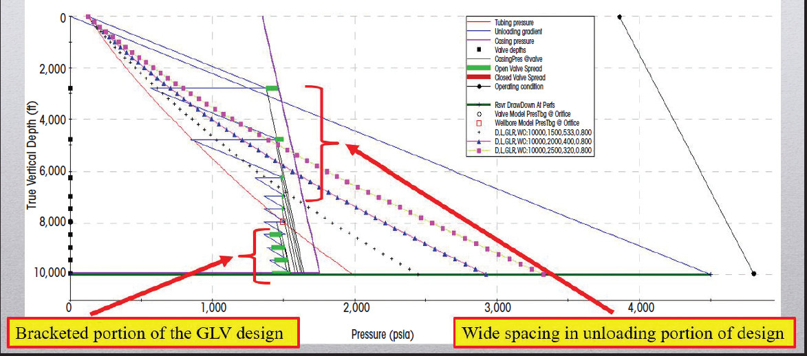
The Austin Chalk horizontal wells of South Texas and Louisiana changed everything in the gas-lift world. The traditional gas-lift design methods used to design vertical wells would not work for horizontal wells. The best gas-lift design method for horizontal Austin Chalk wells is to run unloading valves until reaching a minimum spacing of 152 m (500 ft) (Figure 1) and then continue the 152-m spacing down to the packer. The 152-m spacing is an arbitrary spacing that is not based on engineering principles. A group of gas-lift professionals came up with 152-m spacing by trial and error in the late 1980s. Since it worked in the Austin Chalk horizontal wells, this method was thought to be best for all horizontal wells and adopted by the industry at that time as a “best practice” and has remained the standard today.
Bracketed gas-lift designs
The oil and gas industry naturally had to adjust from mostly vertical wells to the up-and-coming horizontal wells in the 1980s. Many adaptations happened to make downhole tools work horizontally that were designed to work vertically, and those adaptations are still happening today. From completion techniques to artificial lift methods, constant revisions and iterations of tools and designs already in use are taking place.
Following suit, the gas-lift industry had to adapt too. At the time, most gas-lift designs were still being done by hand, and the Austin Chalk horizontal wells performed differently than the vertical wells of yesteryear. They headed terribly and no longer had predictable inflow performance. They made lots of gas, they slugged, made fines and lent themselves to gas lift very well given gas lift thrives in gassy wells producing solids. Many things were tried to lift these wells. Gas-lift valves were run around the corner into the open hole. Dip tubes also were used in an attempt to lower the pressure and make more fluid. Alas, this did not help to make more fluid. Those early attempts to lift these wells worked but were very limited in what they could produce. The next adaptation for horizontal gas lift that was attempted was the bracketed gas-lift design.
Bracketing the valves is a practice where gas-lift valves are run on the tubing at an equal spacing below unloading valves to a depth where nodal analysis shows to be the ideal place to inject gas. This method was typically used in high-rate vertical wells where the productivity index is known and relatively constant.
Bracketing eventually evolved into a standard practice in horizontal wells, because little reservoir information was known. An equal spacing (like 152 m) allows the lift system to remain in the hole and follow a well’s decline without intervention on the well.
Recent flowing BHP surveys have shown that the nodal-based unloading sections of the Austin Chalk designs, with the 152-m brackets, are actually slowing the unloading process and causing problems in unconventional horizontal wells. The unloading valves are routinely spaced too wide, which retards the transfer to the next gas-lift valve and inhibits the unloading process, making the possible drawdown of the formation lessened and hindering early time production. The valves will tend to chatter (open and close very quickly) when they cannot transfer to the next valve and may cause undue fatigue in the bellows. Chattering causes the valves to leak and/or fail in addition to hurting well performance. The surveys identified bad valve spacing as well as communication between the tubing and annulus in places where none should be present, indicating a possible tubing leak of some kind and gave rise to the thought that nodal-based designs may be missing something in unconventional horizontal shale wells.
Nodal-based gas-lift designs
Nodal-based gas-lift designs have previously worked great for traditional vertical wells where nodal analysis is used to create an inflow performance relationship curve to predict well performance and determine the best depth, or point of injection, at which to lift fluid from within a well. Conventional vertical wells typically have a constant BHP, a consistent drive mechanism and support a relatively constant productivity index. In wells like these, the use of nodal analysis to predict well performance and aid in the gas lift design is very common and unmistakably useful. Unfortunately, nodal-based well analysis is not a valid method to predict an unconventional well’s performance over the long term. This method measures a fixed performance point, but today’s shale wells cannot be gauged by this metric. With such rapid decline rates in production, dropping the productivity index and reductions in BHP, unconventional wells change too quickly for nodal to give an accurate answer to the long-term performance model.
Unconventional GLR-based gas lift
The new High Rate Unconventional GLR-Based Gas Lift Method can produce higher rates than typical 152-m bracketed designs and transition from top valve to bottom with ease, using fewer valves.
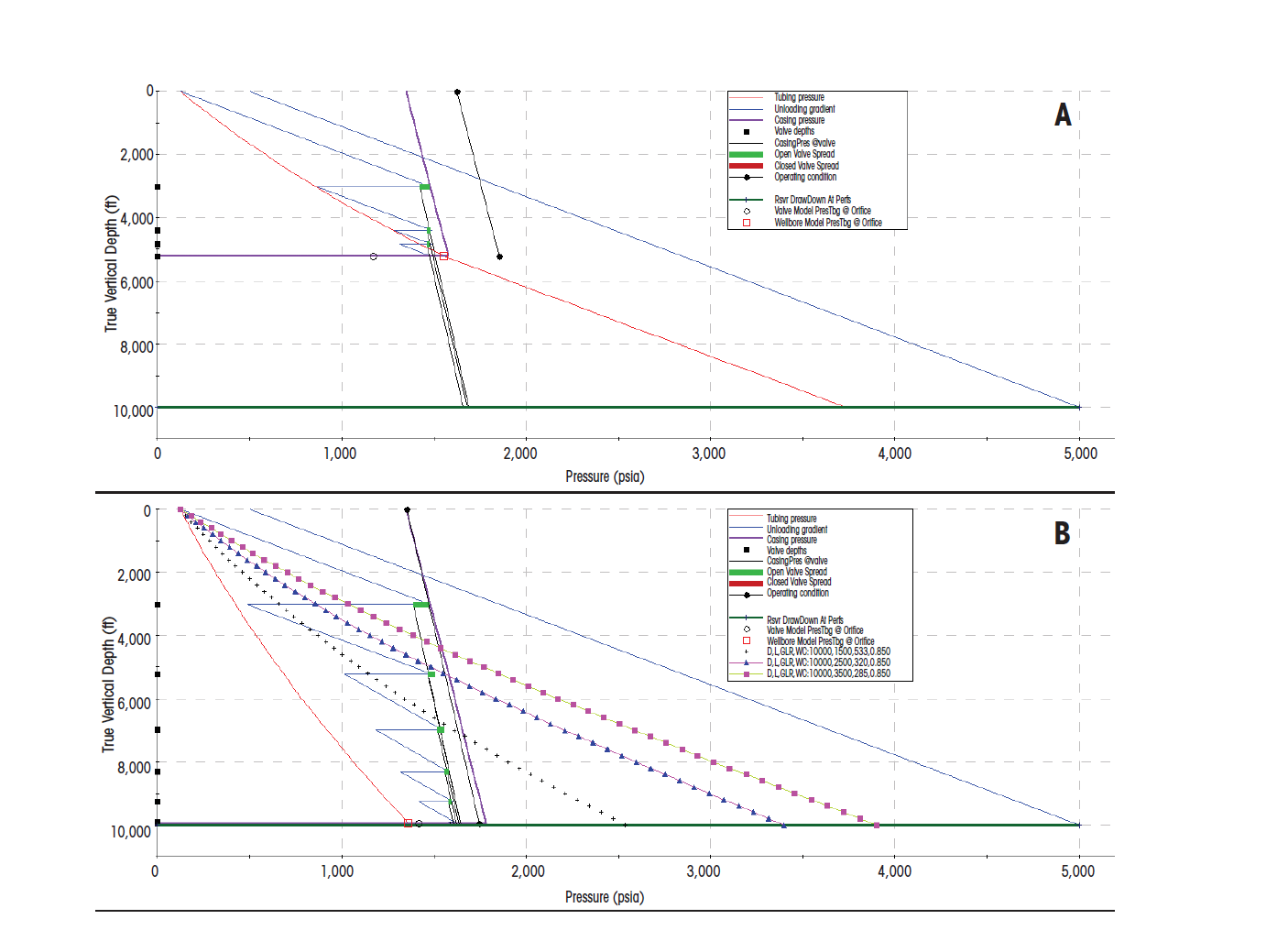
The design works best when the gas-liquid ratio (GLR), static BHP (SBHP), flowing BHP and productivity index are known. With that information, the point of injection can be pinpointed and will determine where the bracketed valves need to start. If the SBHP is known, or merely estimated, and nothing else is available, then the GLR-based method can indeed be used, although it will require some guesswork by the gas-lift designer. The GLR-based design starts by first plotting the SBHP on the graph (Figure 2a) and adding a family of GLR curves (Figure 2b). The bracket is started at the highest rate achievable with the given SBHP and GLR. This is an estimated depth and becomes more accurate as more offset well data are acquired and utilized.
Multipoint injection is considered a bad thing with respect to traditional single-point injection gas lift. Gas-lift valves are primarily a flow control device and, typically, injecting through one at a time is normally desired to get the best well performance.
High-rate gas lift is a nodal-based gas-lift design method introduced in the mid-1980s where gas-lift valves are placed in proximity in the tubing string, sometimes as closely as 30 m (100 ft) apart. Doing so will purposefully cause them to interfere with each other and ultimately keep the valves open. Interference of two valves with one another is known as multipointing. The intention of purposely multipointing is to assist in the injection of higher volumes of gas into the same area while retaining the flexibility of certain valve and port sizes. Shifting from upper to lower valves, the reservoir no longer gives up fluid at the same rate it did initially, thus it’s easier to keep up with unloading and allows transition more slowly from one valve to the next. This provides for the ability to adjust the antiquated 152-m spacing that was arbitrary to begin with and adopt a more modern, tailored and suitable lower valve spacing for unconventional horizontal wells.
Multiple valves open within that close of a proximity allows more gas to be injected easier, introduces more gas in one section of the well, will lighten the fluid column and produce more fluid. This allows the natural reservoir pressure of the formation to become more effective in overcoming the hydrostatic head of the fluid column and push the fluid to the surface. Differential pressure is needed to inject gas through the valve from the higher pressured casing to the lower pressured tubing. A 1-in. port valve is used to inject hundreds of cubic feet of gas into the tubing string and, given ample clearances in the production casing, a 1.5-in. gas-lift valve is typically used too.
“Multipointing is an inefficient use of lift gas and should be eliminated when possible,” said Kenneth Decker of Decker Technology. “The achievement of this goal is based on the assumption that the gas-lift valve has the capacity to flow the required amount of gas to achieve the desired GLR given the current pressure conditions. When lifting from live valves, as is the case when using gas lift early in the life of unconventional wells, the flow performance of the valve is much less than an orifice and, consequently, a single valve is not capable of flowing the volume of gas needed to achieve single-point injection.
“This is particularly true for 1-in. valves and less so for 1.5-in. valves. Trying to achieve single-point injection in an unconventional well while the reservoir pressure is declining rapidly should not be a design goal, nor should time and expense be put forth to remediate multipointing at this time. When the reservoir pressure has declined to a fairly stable value, engineering efforts can be initiated to achieve single-point injection.”
These case study wells were completed with 5.5-in. production casing. As a result, 1.5-in. gas-lift valves cannot be used because that size gas-lift valve requires a larger outer diameter mandrel and will not fit into 5.5- in. production casing when run on 27⁄8-in. production tubing. These unconventional wells require the use of 1-in. gas-lift valves in a 27⁄8-in. tubing mandrel. The valve performance with a 1-in. gas-lift valve will not allow an operator to use ports big enough to inject the gas volumes needed to produce higher rates in these wells.
Spacing several smaller port valves within proximity, multipoint injection will occur and allow an operator to inject enough gas in one area of the well to produce the highest rates possible at depth in unconventional wells. By spacing these unloading valves so closely, the opportunity to transfer down through the valves is sped up; thus, getting to lower valves sooner is possible. This theory takes advantage of the early time production and productivity index of a newer shale well, where production declines are known to be more severe.
Backpressure in a gas-lifted well will reduce the amount of fluid the well can produce, not only now but for the life of the well. Every pound of pressure expended to overcome excess surface tubing pressure is a pound of pressure that could have been lifting fluid. It is very important to conserve the well’s BHP to produce every barrel possible. In gas lift, there is a finite amount of pressure available to lift fluid. Understandably, while many flowing tubing pressures will be limited by surface facilities and in turn will be dictated by sales gas line pressures, getting them as low as possible will have great effects on overall production.
Reducing backpressure is not always easy, and there are many factors that cause backpressure. Flowline size, number of 90-degree turns in a flowline, chokes and distance from the tank battery can all be a cause of excess backpressure, along with many other factors. For the best performance, backpressure should be kept at a minimum and ideally at or below 125 psi.
Conclusion
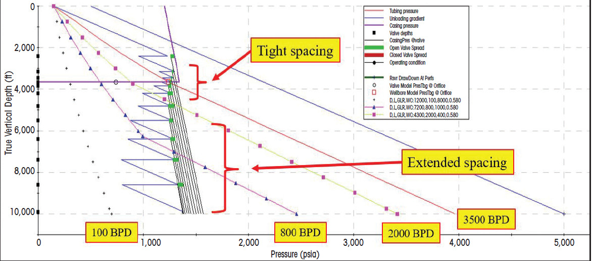
The High Rate Unconventional GLR-Based Gas Lift Method (Figure 3) has plenty of merit in today’s unconventional shale plays. The transition from upper valves to lower valves can be greatly expedited on these unconventional wells by closely spacing the higher valves. This allows the rapid unloading process to create a higher rate in the critical early time of production. It is at this point where the highest natural reservoir pressure is helping the lifting process, and the productivity index will be the greatest in the well’s life. The opposite can be said when getting down to the valves in the lower portion of the well.
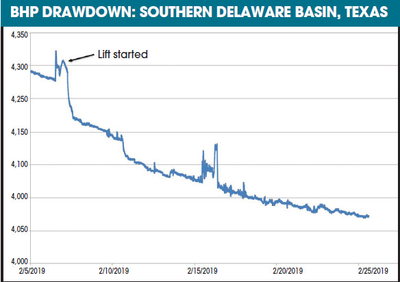
Achieving 2,500-plus bbl/d total fluid rates is well within the grasp of the High Rate Unconventional GLR-Based Method. Utilizing this system, 270-plus psi of drawdown (Figure 4) within several days has been seen following installation of lift. Based on data from an installed BHP gauge, accurate pressures have been tracked and production rates have reached volumes of more than 3,000 bbl/d. All this is from individual wellhead compression in the form of a three-stage 200-hp, gas-powered natural gas compressor with an operating discharge pressure of 1,250 psi.
Continued installations may be needed to gather more conclusive data regarding the broad application of this system. Higher rates can be achieved and fewer valves can be used. There is no need to limit the bottom valves to the tight 152-m spacing based on the status quo or arbitrary existing practices.
Recommended Reading

US Interior Department Releases Offshore Wind Lease Schedule
2024-04-24 - The U.S. Interior Department’s schedule includes up to a dozen lease sales through 2028 for offshore wind, compared to three for oil and gas lease sales through 2029.

Utah’s Ute Tribe Demands FTC Allow XCL-Altamont Deal
2024-04-24 - More than 90% of the Utah Ute tribe’s income is from energy development on its 4.5-million-acre reservation and the tribe says XCL Resources’ bid to buy Altamont Energy shouldn’t be blocked.

Mexico Presidential Hopeful Sheinbaum Emphasizes Energy Sovereignty
2024-04-24 - Claudia Sheinbaum, vying to becoming Mexico’s next president this summer, says she isn’t in favor of an absolute privatization of the energy sector but she isn’t against private investments either.

Venture Global Gets FERC Nod to Process Gas for LNG
2024-04-23 - Venture Global’s massive export terminal will change natural gas flows across the Gulf of Mexico but its Plaquemines LNG export terminal may still be years away from delivering LNG to long-term customers.
US EPA Expected to Drop Hydrogen from Power Plant Rule, Sources Say
2024-04-22 - The move reflects skepticism within the U.S. government that the technology will develop quickly enough to become a significant tool to decarbonize the electricity industry.