Shaped charge designers have improved their thought processes in support of operators and unconventional well stimulations. Perforating systems for the limited-entry stimulation market were traditionally approached by simply making short versions of longer gun systems the industry had always used. A lot has changed.
Those conducting the perforations and those conducting the fracs are communicating. The U.S. activity downturn at the end of 2014, with associated layoffs and company failures, made everybody improve. Operators that had success with direct sourcing (sand and plugs) began talking about other category applications, including perforating. Operators, manufacturers/service companies and the investment community can now easily access and analyze data, both public data and private databases merged to them.
People are analyzing their well results and are forced to consider changes when offsetting acreage performs better. Other contributing factors to perforating change include increasing cluster counts, equipment shortages, higher temperature explosives shortages and the ever-changing trade relations with China and steel tariffs.
Orifice flow equation
In most of today’s designs, it is accepted (perhaps more than it should be) that injectivity rate of fluid follows the orifice flow equation and proppants and fluids move uniformly together. The orifice flow equation is as follows:
ΔP perf = total perforation friction (psi);
Q = flow rate through each perforation (bbl/min);
D = diameter of perforation (in.);
Cv = perforation coefficient; and
ρ = fluid density (lb/gal).
The differential pressure across the casing is the method to treat all the clusters in a stage. Injection rate is primarily influenced by perforation hole diameter to the 4th power. Operators are developing a better understanding of “correct” Cv factors, initial perforation hole sizes and perforation erosion rates during pumping and realizing low treating pressures are not a measure of success.
Engineers are finally abandoning the old rule of thumb of “two barrels per minute per perf” for more robust technical approaches. At a 2-bbl/min injection rate, a .30-in. diameter perforation has an about 1,540-psi differential pressure, whereas a .40-in. hole has about a 480-psi differential. Perforation erosion reduces differential pressure, leading to understimulated clusters. Operators want to know actual perforation hole sizes in their specific weight and grade of casing. The datasheets published by the American Petroleum Institute are of limited value as gun systems are tested in a smaller diameter, lower-grade casing. Industry is increasing testing in P-110 casing in particular and publishing those results. Older style deep-penetrating charges had hole size variation ranging from .50 in. (zero clearance) to .28 in. (maximum clearance) for a 3.125-in. gun inside 5.5-in. P-110 casing. The resulting several-fold variation in injection rate per perforation led operators’ requests for equal-entry hole charges, which gained market acceptance.
Recent trends, changes and why
Equal-entry/equal-shallow penetration charges without carrier centralization have worked extremely well, as have design variations where the charges shoot at an angle to the casing rather than perpendicular. Success has been realized fracturing wells using these style charges, which penetrate very few inches into the formation. Product suppliers now compete on cost, lowest percent hole size variation, number of different sizes they can provide for specific weights and grades of casing, and ability to achieve results through two strings of casing in refracturing applications. Operators can obtain the specific hole size of their request, within about .02 in. This enhances the ability for engineered perforating designs.
Equal-entry hole charges led operators to conduct more step-rate testing and determine perf efficiency/ near wellbore tortuosity. Analysis confidence level increased with known, consistent size holes. Focus has moved to higher differential pressures across the casing. The Society of Petroleum Engineers’ technical papers on “extreme limited-entry,” written by operators routinely designing stimulations with 2,500-psi differential pressures, were well-read and created conversations across industry.
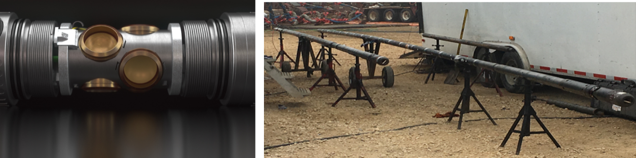
Shaped-charge design accomplished desired hole size results with less explosive weight and smaller charges. This opened up design possibilities including small charges placed beside each other on the same plane, rather than individual, sequential charges in the gun. Field introduction of these gun systems began in 2017, usually in three shot/cluster configurations. These shorter gun assembly length systems having all the perforations in a single plane reduced near-wellbore tortuosity—as step-rate analysis proved. Figure 1 shows information on these systems.
New gun systems, safety and regulations
After the aforementioned turndown in completion activity, stuck gun issues with “blown port plugs” and associated remedial costs escalated. The resulting technology improvement is industry’s migration to disposable systems rather than managing reusable equipment nearing the end of its life. One will continue to see improvement in gun string systems: electric disconnects, data acquisition, gun detonating/hardware components, and especially plug setting tools and “ball-in-place” methodologies. The trend in zonal isolation is increasing where operators pressure test the plug with the ball in place before perforating. It makes operational and economic sense not to pump a whole stage away without a plug holding.
A word of caution: operators’ completion teams are not electronics experts. They rely heavily on service companies for how wireline trucks/downhole electronics components, and especially detonators, function. More explosives accidents and near misses occur than one hears about, and companies with incidents typically do not want to discuss it. Perforating systems have tremendous energy, and one cannot afford a mistake. A few years ago, industry experts estimated greater than 90% of accidents occurred after a misrun. People developing electronics today must ensure systems are highly reliable, properly interface with other components and no misruns occur.
Other trends
Perforating cluster count per stage continues to increase in most basins. The long-term production history is reaching the point where data analytics can determine if economics look as good as early production results indicated with high cluster counts. The northeast U.S., with its gas production, generally has fewer clusters and different geology. Diverters are finding applications.
Operators utilizing higher (1,500 psi or greater after initial erosion) differential pressures generally obtain about 90% perf efficiency. High clay content formations, notably in some areas of Oklahoma, observe lower perf efficiencies.
Perforating hole size is decreasing in the last 18 months. Operators are having success with single, larger holes per cluster.
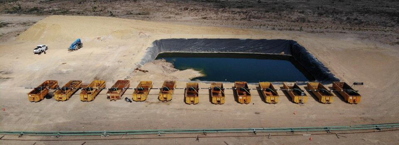
The “gorilla in the room” is associated with particle transport and perf erosion studies. Several universities, operators and a few service companies are trying to better understand how uniformly the proppants move with the fracturing fluids and are progressing numerical simulation. This will lead to a very different thought process and has implications to frac hits and proppant flowback. Figure 2 shows one of the more interesting tests in this arena that a group of operators and others are conducting.
Editor’s note: Phil Snider is a completions consultant to GEODynamics.
Recommended Reading

Defeating the ‘Four Horsemen’ of Flow Assurance
2024-04-18 - Service companies combine processes and techniques to mitigate the impact of paraffin, asphaltenes, hydrates and scale on production—and keep the cash flowing.

Tech Trends: AI Increasing Data Center Demand for Energy
2024-04-16 - In this month’s Tech Trends, new technologies equipped with artificial intelligence take the forefront, as they assist with safety and seismic fault detection. Also, independent contractor Stena Drilling begins upgrades for their Evolution drillship.
AVEVA: Immersive Tech, Augmented Reality and What’s New in the Cloud
2024-04-15 - Rob McGreevy, AVEVA’s chief product officer, talks about technology advancements that give employees on the job training without any of the risks.

Lift-off: How AI is Boosting Field and Employee Productivity
2024-04-12 - From data extraction to well optimization, the oil and gas industry embraces AI.

AI Poised to Break Out of its Oilfield Niche
2024-04-11 - At the AI in Oil & Gas Conference in Houston, experts talked up the benefits artificial intelligence can provide to the downstream, midstream and upstream sectors, while assuring the audience humans will still run the show.